Carbide turning inserts are cutting tools used on lathes and other machine tools to accurately and efficiently remove material from workpieces to create precision parts. Interstate carbide inserts refer to inserts made from tungsten or titanium carbide composites for exceptional hardness and wear resistance properties. This guide provides a comprehensive overview of interstate carbide turning inserts covering application scope, types, selection factors, specifications, usage recommendations, prices, suppliers, FAQs, and more.
Types of Interstate Carbide Turning Inserts
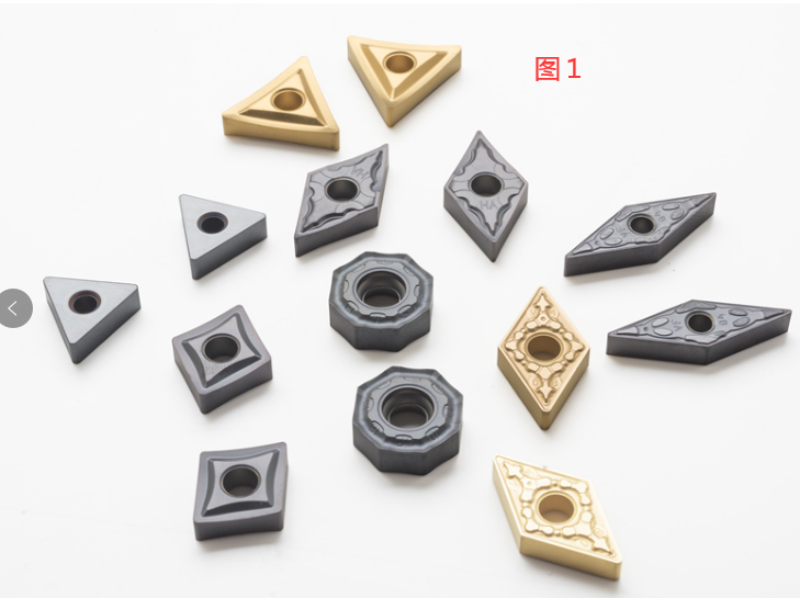
There are several criteria to classify carbide inserts based on ISO standards for tip shape, chipbreaker, tolerance, coating material etc. Common types of interstate carbide inserts include:
| Insert Type | Description | Applications |
|---|---|---|
| Positive | Single-sided insert with positive rake angle suitable for most materials | General purpose roughing and finishing of steels, stainless steels, cast iron etc. |
| Negative | Double-sided insert with negative rake angle for free cutting | Finishing inserts for aluminum, brass, plastics, composites |
| Chamfered | Insert corner is chamfered for strength | Heavy roughing cuts in steels |
| Radiused | Insert corner is rounded to a specific radius | Finishing inserts for fine surface finish requirements |
| Tangential | Top face of insert oriented at an angle (lead angle) to create shearing action | Difficult-to-cut materials like stainless steels, super alloys, hardened steels |
| Chipbreaker | Indentations or grooves on rake face to facilitate chip flow | Most insert types to break the chips for easier chip handling |
The vast range of carbide insert grades and geometries available are optimized for specific workpiece materials and machining operations. Selecting the right insert depends on parameters like – material type, hardness, desired surface finish, depth of cut, feed rate, cutting speed etc.
Interstate Carbide Insert Application Scope
Carbide turning inserts find ubiquitous use in metal cutting applications across industry sectors. Materials cut using carbide inserts include:
- Steels – mild, alloy, tool, die, stainless, cast iron
- Exotic alloys – titanium, hastelloy, waspaloy, inconel, monel
- Non-ferrous – aluminum, brass, bronze
- Plastics, composites
- Woods
Operations performed with carbide turning inserts:
- Roughing – removal of bulk material
- Facing – squaring a surface
- Profiling – complex shapes
- Grooving – cutting grooves
- Parting – separating workpieces
- Boring – enlarging holes
- Threading
- Finishing – final sizing and finishes
Carbide inserts boost productivity in key machining application areas:
| Industry | Components Machined |
|---|---|
| Automotive | Engine blocks, axles, gears, shafts, valves, cylinders |
| Aerospace | Structural forgings, castings, landing gear parts, turbine blades |
| General Engineering | Shafts, valves, couplings, bushings |
| Construction/Mining | Bucket teeth, crusher wear parts, excavator components |
| Agriculture | Plough discs, cultivator points |
| Lumber/Woodworking | Cutting tools |
Carbide Insert Selection Factors
Choosing the best carbide insert depends on numerous parameters pertaining to the workpiece, machining operation, equipment capabilities and product requirements.
Considerations for Carbide Insert Selection
| Consideration | Options | Impact on Insert Selection |
|---|---|---|
| Workpiece Material | Alloy steels, tool steels, stainless steel, Inconel, titanium, aluminum alloys, gray cast iron etc. | Harder work materials require physical properties like Higher wear resistance Greater toughness Ability to resist deformation |
| Type of Machining Operation | Turning operations like Light roughing Heavy interrupted cutting Fine finishing Profiling Grooving Boring etc. | Operation parameters require compatible insert geometries/grades for Positive/negative rake angles Custom chamfers/edge preps Ceramic or CBN grades for best surface finish |
| Hardness of Workpiece Material | Soft forgings, annealed parts Hardened billets, flame or induction hardened parts Through-hardened material Case-hardened parts etc. | With increasing hardness: Need higher hot hardness Must resist abrasive wear Require greater toughness Important to match hardness level |
| Machine Tool Rigidity and Available Power | Engine lathe (7-10 HP) Large CNC lathe (>15 HP) production machine | Higher machine power and stiffness increases depth of cut capability enabling: Use of stronger insert grades Heavier depth of cuts More aggressive feed rates |
| Required Depth of Cut | Finishing passes (~0.010″) Roughing passes (~0.060-0.200″) Heavy hogging (~0.200-0.400″) | With larger depth of cuts: Insert strength becomes vital Must resist higher cutting pressures Alleviate increased heat generation |
| Required Feed Rates | Low/medium/high feed rates | Higher feeds place more mechanical stresses needing: Stronger insert geometries More fracture-resistant substrates/coatings Careful attention to depth of cuts |
| Cutting Speeds | Workpiece material-specific recommended SFM cutting speeds | Matching speeds balances forces between: Optimizing material removal Managing heat generation Preventing rapid wear modes |
| Required Surface Finish | Typical turning surface finishes from: 125-250 microinches Ra roughing 63-125 microinches Ra semi-finishing 32-63 microinches Ra finishing 8-16 microinches Ra super finishing | Finer surface finishes need inserts engineered with: Finer grain carbides Sharp cutting edge radii Optimized edge preps/chamfers Advanced coatings/geometries |
| Type of Coolant Used | Emulsions, water-based or straight oils | Proper coolant selection ensures: Heat and chip flushing at insert/work interface Adequate insert lubrication No work material incompatibility |
| Chip Control Requirements | Long continuous chips, short discontinuous chips | Insert chip control features help: Break up long gummy chips Quickly curl chips to evacuate Prevent chip welding/re-cutting |
| Preferred Insert Shape | Square, diamond, round, triangular, inserted tip cutter etc. | Insert tip shape chosen based on: Type of machining operation Approach angle requirements Desire for added edge strength System-level cutting tool considerations |
Interstate Carbide Insert Specifications
Carbide inserts have detailed ISO specifications encompassing various physical attributes. Below are some key insert specifications to understand when sourcing inserts.
Insert Dimension References
| Parameter | Definition |
|---|---|
| Nose radius – Radius of curvature on insert nose | |
| Tip Geometry | Lead angle – Angle of nose inclination to workpiece |
| Rake angles – Top/side rake angles | |
| Thickness – Thickness along inclination axis | |
| Functional Dimensions | Length/Width – Functional cutting dimensions |
| Hole diameter – Clamping screw fit | |
| Nose height – Height position of insert tip | |
| Grade – Manufacturer grade designation | |
| Identification | Shape – Standard tip shape code |
| Tolerance class – ISO dimensional and form tolerance class |
Coating Types
| Coating | Description |
|---|---|
| TiN | Titanium nitride coating for high hardness and temperature resistance |
| TiCN | Titanium carbonitride coating with improved wear over TiN |
| TiAlN | Titanium aluminum nitride coating with highest hardness and oxidation resistance |
| Al2O3 | Aluminum oxide ceramic coating for high toughness and lubricity |
| DLC | Diamond-like carbon coatings for extremes of wear, friction and corrosion resistance |
Resources are available to cross-reference specifications across inserts from various manufacturers. ISO standards help enable interchangeability of inserts across tooling systems.
Carbide Insert Usage Recommendations
Here are some best practices to follow when using carbide turning inserts for optimal tool life and machining performance:
- Select insert grade based on hardness and toughness required for material
- Ensure insert shape, lead angles, rake angles suit cutting operation
- Use inserts with chipbreakers whenever possible for better chip control
- Choose inserts with radii/chamfers for strengthened cutting edges
- Apply correct insert clamping torque for secure holding
- Strictly adhere to insert handling instructions to prevent chipping
- Store inserts safely in original packaging when not in use
- Use recommended insert feed rates, speeds, and depths of cut
- Employ proper machine cooling and lubrication
- Inspect inserts periodically for flank wear, crater wear etc.
- Replace worn inserts for dimensional accuracy and surface finish
- Consider reusable indexable inserts to minimize costs
- Use inserts rated for most challenging operation parameters for flexibility
Work with carbide insert experts and machine manufacturers to optimize insert selection, tooling systems, and machining parameters.
Price Range of Carbide Inserts
Carbide Insert Price Ranges
| Insert Grade | Price per Insert |
|---|---|
| C1 to C4 (Straight Carbides) | $8 – $225 |
| C5, C6 (Coated Grades) | $12 – $280 |
| Ceramic, CBN, Diamond | Over $300 |
Key Price Drivers
- Carbide substrate and binder – cobalt/nickel alloys pricier
- Coating type/thickness – TiAlN costlier than TiN
- Geometry complexity – positives cheaper than negatives
- Tighter tolerances mean higher cost
- Full face contact inserts pricier than triangular inserts
- Micron grain sizes and uniform carbide costly
- Reputable brand inserts cost more
- Specialized grades much higher priced
- Minimum order quantities affect per insert rate
Carbide inserts can seem expensive but enable vastly increased metal removal rates and tool life versus high speed steel. Payback period can be as little as weeks/months with carbide’s productivity benefits. Consider total operational cost versus just insert cost.
Suppliers of Interstate Carbide Inserts
All major cutting tool manufacturers offer carbide inserts. Some leading interstate suppliers include:
| Company | Grades Offered | USP | |
|---|---|---|---|
| Kennametal | Complete grade range | Industry pioneers in insert technology | |
| Sandvik Coromant | Extensive coverage | Leading innovations in coatings, geometries | |
| Iscar | Precision carbide inserts | Very diverse insert styles | |
| Kyocera | Advanced ceramics focus | Unbeatable performance in niches | |
| Valenite | Standard commercial inserts | Cost-effective general purpose inserts | |
| Garr Tool | Made in USA | Domestic alternative reducing lead times | |
| Mitsubishi Materials | ivarious | grades | Significant presence across segments |
| OSG USA | Application-specific inserts | Emphasizes total tooling solutions |
Interstate inserts are readily available through industrial distributors like MSC Direct, McMaster-Carr, Grainger as well global cutting tool distributors. Pricing is quite competitive across brands. Evaluate insert samples, technical services support, availability etc. besides price during supplier selection.
Installing and Using Carbide Inserts
Insert Installation Tips
| Stage | Guidelines |
|---|---|
| Ensure insert shape matches pocket profile | |
| Insert Preparation | Clear any debris/burrs from insert seating surfaces |
| Check insert for cracks, chipping before use | |
| Select optimal insert clamping torque based on toolholder | |
| Insert Mounting | Evenly tighten screws in sequence to specified torque |
| Ensure insert is fully seated against pocket surfaces | |
| Test insert clamping by attempting to spin insert by hand |
Insert Usage Guidelines
| Aspect | Instructions |
|---|---|
| Always check machine coolant status before start | |
| Machining Setup | Ensure feeds/speeds programmed align with insert limits |
| Test cuts on sample material if unsure of parameters | |
| Employ shortest project cutting lengths whenever possible | |
| During Operation | Listen for inconsistent cutting noise indicating issues |
| Visually check chip flow and coolant stream | |
| Stop machine if chatter, resonance or odd sounds occur | |
| Allow machine to stop completely before measuring workpiece | |
| Post Operation | Carefully clean out swarf debris around toolholder |
| Inspect insert edge condition and measure for wear |
Adhering to best practices when setting up tools, running jobs, and servicing can help realize full productivity from carbide inserts. Partner with tooling experts and machine builders to optimize processes.
Carbide Insert Maintenance
Periodic inspection and preventive maintenance completes the product lifecycle realization with carbide tooling.
| Aspect | Recommended Actions | Purpose/Impact |
|---|---|---|
| Insert Inspection | Inspect cutting edges regularly for: Chipping/fractures Built-up edge (BUE) Flank wear/crater wear | Find issues like edge damage, wear early and: Avoid scrap parts Improve tool life Enhance process capability |
| Insert Handling | Always handle inserts using: Clean gloves Protective trays Original packaging | Careful handling prevents: Insert chipping Contamination leading to poor machining Mixing up various insert grades |
| Insert Storage | Store inserts with focus on: Keeping in original packaging First in – first out (FIFO) stock rotation Clean, dry and stable conditions | Proper storage increases longevity by: Preventing insert corrosion Stopping debris damaging seats Eliminating unused stock with FIFO |
| Insert Disposal | Used inserts should be disposed: Per hazardous material procedures Considering recycling options | End-of-life considerations: Prevent injury from handling worn inserts Extract maximum value from carbide inserts Reduce industrial waste for sustainability |
FAQ
Q: Are carbide inserts suitable for every material?
A: Carbide inserts are exceptionally versatile given the grades available today. However limitations exist for highly abrasive materials better addressed using ceramic or diamond inserts.
Q: Can worn carbide inserts be re-sharpened?
A: Indexable inserts are considered disposable tooling meant for replacement after useful life. Attempts to regrind or re-coat inserts rarely succeed.
Q: How long do carbide inserts last?
A: Carbide insert lifetime depends on work parameters. At optimal speeds and feeds, inserts average 45 to 90 minutes machining time before reaching wear limits. Rigorous applications may consume inserts faster.
Q: What causes premature insert failure?
A: Improper insert selection/use relative to work material/operation, underpowered machine tools, excessive/interrupted cuts, built-up edge, poor chip control, improper clamping, damaged tool holders etc.
Q: Should carbide inserts be stored in a freezer?
A: Freezing is not necessary. Simply keep inserts contamination and corrosion-free in a stable indoor environment away from temperature extremes.
Q: What are typical surface finishes from carbide inserts?
A: New sharp inserts can achieve 8 to 15 micron Ra finishes. As inserts wear, typical surface finishes are 15 to 25+ micron Ra for roughing and 25 to 60+ micron Ra for finishing.