- Carbide Insert

Carbide Insert
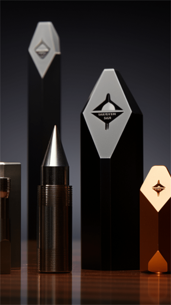
Carbide inserts are cutting tools used in machining operations, such as turning, milling, and drilling. They are made from a combination of tungsten carbide and a metallic binder, typically cobalt or nickel. The inserts have a distinct geometric shape with multiple cutting edges, allowing for efficient material removal and precise machining.
Carbide inserts offer several advantages over traditional high-speed steel tools. The hardness and wear resistance of tungsten carbide make the inserts highly durable, allowing for extended tool life and reduced downtime. They can withstand high cutting speeds and temperatures, resulting in faster machining and improved productivity.
The metallic binder provides toughness and strength to the inserts, preventing chipping or fracturing during cutting operations. This enhances the reliability and stability of the inserts, especially when subjected to heavy loads and high-impact forces.
Contact us if what you need is not shown here.
Introduction
Carbide inserts are cutting tools used in machining operations for turning, milling, and drilling. Made of tungsten carbide and a metallic binder, these inserts provide exceptional hardness, wear resistance, and durability. With their multiple cutting edges and various shapes, carbide inserts enable efficient material removal and precise machining, making them essential components in modern manufacturing processes.
Composition and Structure
Carbide inserts are composed of a material called cemented carbide, which is a combination of tungsten carbide (WC) particles and a metallic binder, typically cobalt (Co). The composition and structure of carbide inserts play a crucial role in their performance and durability.
The structure of carbide inserts consists of tungsten carbide particles dispersed within a cobalt matrix. The tungsten carbide particles form the cutting edges and wear-resistant regions of the inserts, while the cobalt matrix provides support and toughness.

Hardness
Carbide inserts are exceptionally hard, often ranking higher on the Mohs scale of hardness compared to other cutting materials.
Wear Resistance
Carbide inserts exhibit excellent wear resistance, even when cutting through tough materials or at high cutting speeds.
Toughness
The metallic binder, typically cobalt, adds toughness and impact resistance to the inserts, preventing chipping or fracturing during machining operations.
Heat Resistance
Withstands high temperatures generated during cutting without compromising performance.
Cutting Performance
Carbide inserts offer high cutting performance, delivering efficient material removal rates, improved surface finish, and dimensional accuracy.
Versatility
Carbide inserts are versatile tools that can be used for machining various materials, including steels, stainless steels, cast iron, aluminum, and exotic alloys.
Chip Control
Carbide inserts are designed to provide effective chip control during machining operations.
Coatability
Carbide inserts can be coated with specialized coatings such as titanium nitride (TiN) or titanium carbonitride (TiCN) to further enhance their properties.
Powder Preparation
Tungsten carbide and metallic binder powders, such as cobalt or nickel, are prepared separately.
Mixing
The tungsten carbide and metallic binder powders are carefully mixed in precise proportions.
Compacting
The mixed powder is placed into a die and subjected to high pressure using a hydraulic press. This compacts the powder into the desired insert shape.
Pre-Sintering
The compacted inserts undergo pre-sintering in a furnace. This low-temperature process removes binders and enhances the green strength of the inserts.
Shaping
The pre-sintered inserts are machined or ground to achieve the final shape, dimensions, and cutting edge geometry. This step requires precision to ensure accurate cutting performance.
Final Sintering
The shaped inserts are subjected to high-temperature sintering in a furnace. This process allows the tungsten carbide particles to bond together, forming a solid structure with the metallic binder.
Grinding and Finishing
The sintered inserts undergo grinding and finishing operations to refine the cutting edges, remove any imperfections, and achieve the desired surface finish.
Coating (Optional)
Some carbide inserts may undergo coating processes to enhance their properties. These coatings improve wear resistance, reduce friction, and extend tool life.
Turning
Carbide inserts are extensively used in turning operations, which involve removing material from a rotating workpiece. They provide efficient and precise cutting, making them ideal for tasks such as cylindrical turning, facing, grooving, and threading.
Milling
Carbide inserts are commonly employed in milling operations, where material is removed using rotating multi-point cutting tools. They are used for tasks such as face milling, shoulder milling, slotting, and contouring. Carbide inserts enable high-speed machining and deliver superior surface finishes.
Drilling
Carbide inserts are utilized in drilling operations to create holes in various materials. They offer excellent cutting performance and stability during drilling processes. Carbide inserts are suitable for both traditional drilling and more advanced techniques like indexable drilling.
Parting and Grooving
Carbide inserts are frequently used in parting and grooving applications, which involve cutting off or creating grooves on workpieces. They provide precise and reliable cutting, allowing for efficient operations in industries such as automotive, aerospace, and general engineering.
A tungsten carbide insert is a cutting tool made from tungsten carbide, a material known for its incredible hardness and wear resistance. These inserts are used in machining processes to cut, shape, and finish various materials, including metals and composites. They are highly valued for their ability to maintain a sharp cutting edge even under extreme conditions.
Yes, tungsten carbide inserts can be resharpened, but the process requires specialized equipment and expertise. Resharpening can extend the tool’s life and maintain cutting performance, but it is often more cost-effective to replace the inserts.
Boring inserts can machine a wide range of materials, including steels, cast irons, non-ferrous metals, plastics, and composites. Their high hardness makes them particularly effective for cutting tough and abrasive materials.
- Increased Wear Resistance: Coatings like TiN or TiAlN extend tool life.
- Enhanced Performance: Better heat resistance and reduced friction.
- Higher Cutting Speeds: Allow for faster machining processes.
- Improved Surface Finish: Produces smoother and more precise cuts.
- Versatility: Suitable for a wide range of materials and applications.
Store inserts in a clean, dry environment, protected from impact, moisture, and extreme temperatures. Use appropriate chip brushes and cleaning methods to remove chips and debris after each use. Proper storage and maintenance can significantly extend the life of your inserts and ensure consistent performance.
Consider the material being machined (hardness, machinability), the type of turning operation (roughing, finishing), the desired tool life, and the cutting parameters (speed, feed, depth of cut). Consult supplier catalogs, online resources, or seek expert advice to determine the most suitable grade.
Threading inserts for turning are indexable cutting tools specifically engineered to machine external and internal threads on lathes or turning centers. Unlike their counterparts used for general turning operations, threading inserts feature precisely ground cutting edges that correspond to the desired thread form, pitch, and diameter. This specialized geometry allows for the efficient and accurate creation of threads in a single pass or multiple passes, depending on the thread specifications and material being machined.
- Turning Operations: For precise metal cutting and shaping.
- Milling: In both face and end milling tasks.
- Drilling: To enhance tool life and performance.
- Boring: For accurate hole enlarging.
- Grooving and Threading: In industrial machining.
Selecting the appropriate rake angle depends on the material being machined and the desired cutting conditions. Softer materials and finishing operations generally benefit from positive rake angles, while harder materials and roughing operations often require negative rake angles.
Lorem ipsum dolor sit amet, consectetur adipisicing elit. Optio, neque qui velit. Magni dolorum quidem ipsam eligendi, totam, facilis laudantium cum accusamus ullam voluptatibus commodi numquam, error, est. Ea, consequatur.
The number of flutes affects the cutting performance and material removal rate. Fewer flutes provide better chip evacuation, which is important for non-ferrous metals that tend to generate longer chips. However, more flutes can offer smoother cuts and better finishes. The choice depends on the specific material and the milling operation.
The optimal number of flutes depends on factors like material being machined, desired surface finish, and available spindle power. More flutes generally provide smoother finishes and higher material removal rates but require increased spindle speed and power.
Signs of wear include increased cutting forces, surface finish degradation, and chip welding. Optimize cutting parameters, ensure proper coolant application, and avoid excessive tool overhang to extend tool life.
- Milling: For contouring, slotting, and pocketing.
- Die and Mold Making: Precise shaping and finishing.
- Aerospace and Automotive: High-performance material removal.
- Medical Devices: Precision machining of complex parts.
- Prototyping: Creating detailed and intricate designs.
Cemented carbide end mills offer significantly greater hardness, wear resistance, and heat resistance compared to HSS end mills. This translates to extended tool life, higher cutting speeds, increased material removal rates, and the ability to machine harder materials.
Solid carbide end mills can cut a wide range of materials, including steel, stainless steel, aluminum, titanium, and composites. Their hardness and wear resistance make them suitable for both soft and hard materials.
3 flute end mills offer a better balance between chip evacuation and surface finish compared to 2 flute end mills. They generally produce a smoother surface finish while still providing efficient chip removal in many materials, making them versatile for various applications.
2 flute end mills excel in efficient chip evacuation, particularly in softer materials, and allow for higher cutting speeds and feed rates due to reduced cutting edge contact. This translates to faster machining times and increased productivity.
4 flute end mills offer increased stability, improved chip evacuation, and generally smoother surface finishes compared to 2 flute end mills. This makes them well-suited for a wider range of materials and machining operations, particularly when higher cutting forces are involved.
Turning Inserts Data
Turning Carbide Insert Description
A turning carbide insert is a small, specialized cutting tool used in turning operations. It features a hard carbide tip or insert that is designed for cutting, shaping, and finishing the outer surface of a workpiece. The carbide insert is securely mounted on a tool holder or clamp, allowing it to rotate and engage with the workpiece.
Turning carbide inserts are specifically designed for lathe machines and are commonly used in metalworking applications. They are known for their exceptional hardness, wear resistance, and ability to withstand high cutting speeds. The carbide tip is engineered with multiple cutting edges, enabling efficient material removal and precise turning operations.

| Insert shape | Type | Dimension (mm) | Grade | ||||||||||||||
|---|---|---|---|---|---|---|---|---|---|---|---|---|---|---|---|---|---|
| P | M | K | H | Cermet | |||||||||||||
| ΦI.C | L | S | Φd | Re | TP15S | TP15T | TP25S | TP25T | TA20F | TA10A | TM20R | TK10R | TA05A | TMC20 | TMC35 | ||
 |
TCNMA120404 | 12.7 | 12.9 | 4.76 | 5.16 | 0.4 | ● | ||||||||||
| TCNMA120408 | 12.7 | 12.9 | 4.76 | 5.16 | 0.8 | ● | |||||||||||
| TCNMA120412 | 12.7 | 12.9 | 4.76 | 5.16 | 1.2 | ● | |||||||||||
| TCNMA160608 | 16.1 | 15.9 | 6.35 | 6.35 | 0.8 | ● | |||||||||||
 |
TCNMG120404-KN5 | 12.7 | 12.9 | 4.76 | 5.16 | 0.4 | ● | ||||||||||
| TCNMG120408-KN5 | 12.7 | 12.9 | 4.76 | 5.16 | 0.8 | ● | |||||||||||
| TCNMG120412-KN5 | 12.7 | 12.9 | 4.76 | 5.16 | 1.2 | ● | |||||||||||
| TCNMG160608-KN5 | 16.1 | 15.9 | 6.35 | 6.35 | 0.8 | ● | |||||||||||
 |
TCNMG120404-PM4 | 12.7 | 12.9 | 4.76 | 5.16 | 0.4 | ● | ● | |||||||||
| TCNMG120408-PM4 | 12.7 | 12.9 | 4.76 | 5.16 | 0.8 | ◐ | ● | ● | ● | ||||||||
| TCNMG120412-PM4 | 12.7 | 12.9 | 4.76 | 5.16 | 1.2 | ◐ | ● | ● | ● | ||||||||
 |
TCNMG120404-SM3 | 12.7 | 12.9 | 4.76 | 5.16 | 0.4 | ● | ◐ | |||||||||
| TCNMG120408-SM3 | 12.7 | 12.9 | 4.76 | 5.16 | 0.8 | ● | ◐ | ||||||||||
| TCNMG120412-SM3 | 12.7 | 12.9 | 4.76 | 5.16 | 1.2 | ● | ◐ | ||||||||||
 |
TCNMG120404-HS2 | 12.7 | 12.9 | 4.76 | 5.16 | 0.4 | ◐ | ● | |||||||||
| TCNMG120408-HS2 | 12.7 | 12.9 | 4.76 | 5.16 | 0.8 | ◐ | ● | ||||||||||
| TCNMG120412-HS2 | 12.7 | 12.9 | 4.76 | 5.16 | 1.2 | ◐ | ● | ||||||||||
 |
TCNMG120404-PM3 | 12.7 | 12.9 | 4.76 | 5.16 | 0.4 | ◐ | ● | |||||||||
| TCNMG120408-PM3 | 12.7 | 12.9 | 4.76 | 5.16 | 0.8 | ◐ | ● | ||||||||||
| TCNMG120412-PM3 | 12.7 | 12.9 | 4.76 | 5.16 | 1.2 | ◐ | ● | ||||||||||
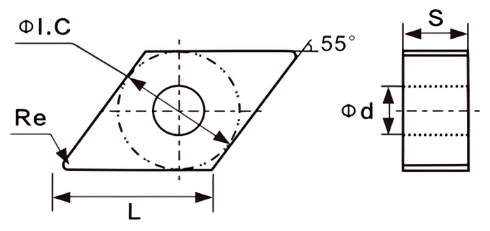
| Insert shape | Type | Dimension (mm) | Grade | ||||||||||||||
|---|---|---|---|---|---|---|---|---|---|---|---|---|---|---|---|---|---|
| P | M | K | H | Cermet | |||||||||||||
| ΦI.C | L | S | Φd | Re | TP15S | TP15T | TP25S | TP25T | TA20F | TA10A | TM20R | TK10R | TA05A | TMC20 | TMC35 | ||
 |
DNMA150404 | 12.7 | 15.5 | 4.76 | 5.16 | 0.4 | ● | ||||||||||
| DNMA150408 | 12.7 | 15.5 | 4.76 | 5.16 | 0.8 | ● | |||||||||||
| DNMA150604 | 12.7 | 15.5 | 6.35 | 5.16 | 0.4 | ● | |||||||||||
| DNMA150608 | 12.7 | 15.5 | 6.35 | 5.16 | 0.8 | ● | |||||||||||
 |
DNMG150404-KN5 | 12.7 | 15.5 | 4.76 | 5.16 | 0.4 | ● | ||||||||||
| DNMG150408-KN5 | 12.7 | 15.5 | 4.76 | 5.16 | 0.8 | ● | |||||||||||
| DNMG150604-KN5 | 12.7 | 15.5 | 6.35 | 5.16 | 0.4 | ● | |||||||||||
| DNMG150608-KN5 | 12.7 | 15.5 | 6.35 | 5.16 | 0.8 | ● | |||||||||||
 |
DNMG150404-PM4 | 12.7 | 15.5 | 4.76 | 5.16 | 0.4 | ● | ● | |||||||||
| DNMG150408-PM4 | 12.7 | 15.5 | 4.76 | 5.16 | 0.8 | ◐ | ● | ● | ● | ||||||||
| DNMG150604-PM4 | 12.7 | 15.5 | 6.35 | 5.16 | 0.4 | ◐ | ● | ● | ● | ||||||||
| DNMG150608-PM4 | 12.7 | 15.5 | 6.35 | 5.16 | 0.8 | ◐ | ● | ● | ● | ||||||||
 |
DNMG150404-SM3 | 12.7 | 15.5 | 4.76 | 5.16 | 0.4 | ● | ◐ | |||||||||
| DNMG150408-SM3 | 12.7 | 15.5 | 4.76 | 5.16 | 0.8 | ● | ◐ | ||||||||||
| DNMG150604-SM3 | 12.7 | 15.5 | 6.35 | 5.16 | 0.4 | ● | ◐ | ||||||||||
| DNMG150608-SM3 | 12.7 | 15.5 | 6.35 | 5.16 | 0.8 | ● | ◐ | ||||||||||
 |
DNMG150404-HS2 | 12.7 | 15.5 | 4.76 | 5.16 | 0.4 | ◐ | ● | |||||||||
| DNMG150408-HS2 | 12.7 | 15.5 | 4.76 | 5.16 | 0.8 | ◐ | ● | ||||||||||
| DNMG150604-HS2 | 12.7 | 15.5 | 6.35 | 5.16 | 0.4 | ◐ | ● | ||||||||||
| DNMG150608-HS2 | 12.7 | 15.5 | 6.35 | 5.16 | 0.8 | ◐ | ● | ||||||||||
 |
DNMG150404-PM3 | 12.7 | 15.5 | 4.76 | 5.16 | 0.4 | ◐ | ● | |||||||||
| DNMG150408-PM3 | 12.7 | 15.5 | 4.76 | 5.16 | 0.8 | ◐ | ● | ||||||||||
| DNMG150604-PM3 | 12.7 | 15.5 | 6.35 | 5.16 | 0.4 | ◐ | ● | ||||||||||
| DNMG150608-PM3 | 12.7 | 15.5 | 6.35 | 5.16 | 0.8 | ◐ | ● | ||||||||||
 |
DNMG150604L-VF | 12.7 | 15.5 | 6.35 | 5.16 | 0.4 | ◐ | ● | |||||||||
| DNMG150604R-VF | 12.7 | 15.5 | 6.35 | 5.16 | 0.8 | ◐ | ● | ||||||||||
| DNMG150608L-VF | 12.7 | 15.5 | 6.35 | 5.16 | 0.4 | ◐ | ● | ||||||||||
| DNMG150608R-VF | 12.7 | 15.5 | 6.35 | 5.16 | 0.8 | ◐ | ● | ||||||||||

| Insert shape | Type | Dimension (mm) | Grade | ||||||||||||||
|---|---|---|---|---|---|---|---|---|---|---|---|---|---|---|---|---|---|
| P | M | K | H | Cermet | |||||||||||||
| ΦI.C | L | S | Φd | Re | TP15S | TP15T | TP25S | TP25T | TA20F | TA10A | TM20R | TK10R | TA05A | TMC20 | TMC35 | ||
 |
TSNMA120404 | 12.7 | 12.7 | 4.76 | 5.16 | 0.4 | ● | ||||||||||
| TSNMA120408 | 12.7 | 12.7 | 4.76 | 5.16 | 0.8 | ● | |||||||||||
| TSNMA150608 | 15.875 | 15.875 | 6.35 | 6.35 | 0.8 | ● | |||||||||||
| TSNMA150612 | 15.875 | 15.875 | 6.35 | 6.35 | 1.2 | ● | |||||||||||
 |
TSNMG120404-KN5 | 12.7 | 12.7 | 4.76 | 5.16 | 0.4 | ● | ||||||||||
| TSNMG120408-KN5 | 12.7 | 12.7 | 4.76 | 5.16 | 0.8 | ● | |||||||||||
| TSNMG150608-KN5 | 15.875 | 15.875 | 6.35 | 6.35 | 0.8 | ● | |||||||||||
| TSNMG150612-KN5 | 15.875 | 15.875 | 6.35 | 6.35 | 1.2 | ● | |||||||||||
 |
TSNMG120404-PM4 | 12.7 | 12.7 | 4.76 | 5.16 | 0.4 | ● | ● | |||||||||
| TSNMG120408-PM4 | 12.7 | 12.7 | 4.76 | 5.16 | 0.8 | ◐ | ● | ● | ● | ||||||||
| TSNMG150608-PM4 | 15.875 | 15.875 | 6.35 | 6.35 | 0.8 | ● | ● | ||||||||||
| TSNMG150612-PM4 | 15.875 | 15.875 | 6.35 | 6.35 | 1.2 | ● | ● | ||||||||||
 |
TSNMG120404-SM3 | 12.7 | 12.7 | 4.76 | 5.16 | 0.4 | ● | ◐ | |||||||||
| TSNMG120408-SM3 | 12.7 | 12.7 | 4.76 | 5.16 | 0.8 | ● | ◐ | ||||||||||
| TSNMG150608-SM3 | 15.875 | 15.875 | 6.35 | 6.35 | 0.8 | ● | ◐ | ||||||||||
| TSNMG150612-SM3 | 15.875 | 15.875 | 6.35 | 6.35 | 1.2 | ● | ◐ | ||||||||||
 |
TSNMG120404-HS2 | 12.7 | 12.7 | 4.76 | 5.16 | 0.4 | ◐ | ● | |||||||||
| TSNMG120408-HS2 | 12.7 | 12.7 | 4.76 | 5.16 | 0.8 | ◐ | ● | ||||||||||
| TSNMG150608-HS2 | 15.875 | 15.875 | 6.35 | 6.35 | 0.8 | ◐ | ● | ||||||||||
| TSNMG150612-HS2 | 15.875 | 15.875 | 6.35 | 6.35 | 1.2 | ◐ | ● | ||||||||||
 |
TSNMG120404-PM3 | 12.7 | 12.7 | 4.76 | 5.16 | 0.4 | ◐ | ● | |||||||||
| TSNMG120408-PM3 | 12.7 | 12.7 | 4.76 | 5.16 | 0.8 | ◐ | ● | ||||||||||
| TSNMG120412-PM3 | 12.7 | 12.7 | 4.76 | 5.16 | 1.2 | ◐ | ● | ||||||||||

| Insert shape | Type | Dimension (mm) | Grade | ||||||||||||||
|---|---|---|---|---|---|---|---|---|---|---|---|---|---|---|---|---|---|
| P | M | K | H | Cermet | |||||||||||||
| ΦI.C | L | S | Φd | Re | TP15S | TP15T | TP25S | TP25T | TA20F | TA10A | TM20R | TK10R | TA05A | TMC20 | TMC35 | ||
 |
TTNMA160404 | 9.525 | 16.5 | 4.76 | 3.81 | 0.4 | ● | ||||||||||
| TTNMA160408 | 9.525 | 16.5 | 4.76 | 3.81 | 0.8 | ● | |||||||||||
| TTNMA220408 | 12.7 | 22 | 4.76 | 5.16 | 0.8 | ● | |||||||||||
| TTNMA220412 | 12.7 | 22 | 4.76 | 5.16 | 1.2 | ● | |||||||||||
 |
TTNMG160404-KN5 | 9.525 | 16.5 | 4.76 | 3.81 | 0.4 | ● | ||||||||||
| TTNMG160408-KN5 | 9.525 | 16.5 | 4.76 | 3.81 | 0.8 | ● | |||||||||||
| TTNMG220408-KN5 | 12.7 | 22 | 4.76 | 5.16 | 0.8 | ● | |||||||||||
| TTNMG220412-KN5 | 12.7 | 22 | 4.76 | 5.16 | 1.2 | ● | |||||||||||
 |
TTNMG160404-PM4 | 9.525 | 16.5 | 4.76 | 3.81 | 0.4 | ● | ● | |||||||||
| TTNMG160408-PM4 | 9.525 | 16.5 | 4.76 | 3.81 | 0.8 | ◐ | ● | ● | ● | ||||||||
| TTNMG220408-PM4 | 12.7 | 22 | 4.76 | 5.16 | 0.8 | ● | ● | ||||||||||
| TTNMG220412-PM4 | 12.7 | 22 | 4.76 | 5.16 | 1.2 | ● | ● | ||||||||||
 |
TTNMG160404-SM3 | 9.525 | 16.5 | 4.76 | 3.81 | 0.4 | ● | ◐ | |||||||||
| TTNMG160408-SM3 | 9.525 | 16.5 | 4.76 | 3.81 | 0.8 | ● | ◐ | ||||||||||
| TTNMG220408-SM3 | 12.7 | 22 | 4.76 | 5.16 | 0.8 | ● | ◐ | ||||||||||
| TTNMG220412-SM3 | 12.7 | 22 | 4.76 | 5.16 | 1.2 | ● | ◐ | ||||||||||
 |
TTNMG160404-HS2 | 9.525 | 16.5 | 4.76 | 3.81 | 0.4 | ● | ◐ | |||||||||
| TTNMG160408-HS2 | 9.525 | 16.5 | 4.76 | 3.81 | 0.8 | ● | ◐ | ||||||||||
| TTNMG160412-HS2 | 9.525 | 16.5 | 4.76 | 3.81 | 1.2 | ● | ◐ | ||||||||||
 |
TTNMG160404-PM3 | 9.525 | 16.5 | 4.76 | 3.81 | 0.4 | ● | ◐ | |||||||||
| TTNMG160408-PM3 | 9.525 | 16.5 | 4.76 | 3.81 | 0.8 | ● | ◐ | ||||||||||
| TTNMG160412-PM3 | 9.525 | 16.5 | 4.76 | 3.81 | 1.2 | ● | ◐ | ||||||||||
 |
TTNMG160404R-VF | 9.525 | 16.5 | 4.76 | 3.81 | 0.4 | ◐ | ● | |||||||||
| TTNMG160404L-VF | 9.525 | 16.5 | 4.76 | 3.81 | 0.4 | ◐ | ● | ||||||||||
 |
TTNMG160404R-JP | 9.525 | 16.5 | 4.76 | 3.81 | 0.4 | ● | ||||||||||
| TTNMG160404L-JP | 9.525 | 16.5 | 4.76 | 3.81 | 0.4 | ● | |||||||||||
| TTNMG160408R-JP | 9.525 | 16.5 | 4.76 | 3.81 | 0.8 | ● | |||||||||||
| TTNMG160408L-JP | 9.525 | 16.5 | 4.76 | 3.81 | 0.8 | ● | |||||||||||
 |
TTNGG160402R-S | 9.525 | 16.5 | 4.76 | 3.81 | 0.2 | ● | ◐ | ● | ||||||||
| TTNGG160402L-S | 9.525 | 16.5 | 4.76 | 3.81 | 0.2 | ● | ◐ | ● | |||||||||
| TTNGG160404R-S | 9.525 | 16.5 | 4.76 | 3.81 | 0.4 | ● | ◐ | ● | |||||||||
| TTNGG160404L-S | 9.525 | 16.5 | 4.76 | 3.81 | 0.4 | ● | ◐ | ● | |||||||||
 |
TTNGG160402R-C | 9.525 | 16.5 | 4.76 | 3.81 | 0.2 | ● | ◐ | ● | ||||||||
| TTNGG160402L-C | 9.525 | 16.5 | 4.76 | 3.81 | 0.2 | ● | ◐ | ● | |||||||||
| TTNGG160404R-C | 9.525 | 16.5 | 4.76 | 3.81 | 0.4 | ● | ◐ | ● | |||||||||
| TTNGG160404L-C | 9.525 | 16.5 | 4.76 | 3.81 | 0.4 | ● | ◐ | ● | |||||||||

| Insert shape | Type | Dimension (mm) | Grade | ||||||||||||||
|---|---|---|---|---|---|---|---|---|---|---|---|---|---|---|---|---|---|
| P | M | K | H | Cermet | |||||||||||||
| ΦI.C | L | S | Φd | Re | TP15S | TP25S | TP25T | TP40S | TA20F | TA10A | TM20R | TK10R | TA05A | TMC20 | TMC35 | ||
| TVNMG160404-PM4 | 9.525 | 16.6 | 4.76 | 3.81 | 0.4 | ● | ● | ||||||||||
| TVNMG160408-PM4 | 9.525 | 16.6 | 4.76 | 3.81 | 0.8 | ● | ● | ||||||||||
| TVNMG160412-PM4 | 9.525 | 16.6 | 4.76 | 3.81 | 1.2 | ● | ● | ||||||||||
| TVNMG160404-SM3 | 9.525 | 16.6 | 4.76 | 3.81 | 0.4 | ● | ◐ | ||||||||||
| TVNMG160408-SM3 | 9.525 | 16.6 | 4.76 | 3.81 | 0.8 | ● | ◐ | ||||||||||
| TVNMG160404-HS2 | 9.525 | 16.6 | 4.76 | 3.81 | 0.4 | ◐ | ● | ||||||||||
| TVNMG160408-HS2 | 9.525 | 16.6 | 4.76 | 3.81 | 0.8 | ◐ | ● | ||||||||||
| TVNMG160412-HS2 | 9.525 | 16.6 | 4.76 | 3.81 | 1.2 | ◐ | ● | ||||||||||
 |
TVNGG160404R-H | 9.525 | 16.6 | 4.76 | 3.81 | 0.4 | ◐ | ● | |||||||||
| TVNGG160404L-H | 9.525 | 16.6 | 4.76 | 3.81 | 0.4 | ◐ | ● | ||||||||||
| TVNGG160404R-F | 9.525 | 16.6 | 4.76 | 3.81 | 0.4 | ◐ | ● | ||||||||||
| TVNGG160404L-F | 9.525 | 16.6 | 4.76 | 3.81 | 0.4 | ◐ | ● | ||||||||||
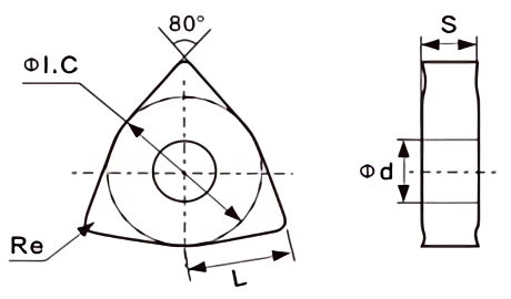
| Insert shape | Type | Dimension (mm) | Grade | ||||||||||||||
|---|---|---|---|---|---|---|---|---|---|---|---|---|---|---|---|---|---|
| P | M | K | H | Cermet | |||||||||||||
| ΦI.C | L | S | Φd | Re | TP15S | TP15T | TP25S | TP25T | TA20F | TA10A | TM20R | TK10R | TA05A | TMC20 | TMC35 | ||
 |
TWNMA080404 | 12.7 | 8.7 | 4.76 | 5.16 | 0.4 | ● | ||||||||||
| TWNMA080408 | 12.7 | 8.7 | 4.76 | 5.16 | 0.8 | ● | |||||||||||
| TWNMA080412 | 12.7 | 8.7 | 4.76 | 5.16 | 1.2 | ● | |||||||||||
 |
TWNMG080404-PM4 | 12.7 | 8.7 | 4.76 | 5.16 | 0.4 | ● | ● | |||||||||
| TWNMG080408-PM4 | 12.7 | 8.7 | 4.76 | 5.16 | 0.8 | ◐ | ● | ● | ● | ||||||||
| TWNMG080412-PM4 | 12.7 | 8.7 | 4.76 | 5.16 | 1.2 | ◐ | ● | ● | ● | ||||||||
 |
TWNMG080404-SM3 | 12.7 | 8.7 | 4.76 | 5.16 | 0.4 | ● | ◐ | |||||||||
| TWNMG080408-SM3 | 12.7 | 8.7 | 4.76 | 5.16 | 0.8 | ● | ◐ | ||||||||||
| TWNMG080412-SM3 | 12.7 | 8.7 | 4.76 | 5.16 | 1.2 | ● | ◐ | ||||||||||
 |
TWNMG080404-HS2 | 12.7 | 8.7 | 4.76 | 5.16 | 0.4 | ● | ◐ | |||||||||
| TWNMG080408-HS2 | 12.7 | 8.7 | 4.76 | 5.16 | 0.8 | ● | ◐ | ||||||||||
| TWNMG080412-HS2 | 12.7 | 8.7 | 4.76 | 5.16 | 1.2 | ● | ◐ | ||||||||||
 |
TWNMG080404-PM3 | 12.7 | 8.7 | 4.76 | 5.16 | 0.4 | ● | ◐ | |||||||||
| TWNMG080408-PM3 | 12.7 | 8.7 | 4.76 | 5.16 | 0.8 | ● | ◐ | ||||||||||
| TWNMG080412-PM3 | 12.7 | 8.7 | 4.76 | 5.16 | 1.2 | ● | ◐ | ||||||||||
 |
TWNMG080404R-JP | 12.7 | 8.7 | 4.76 | 5.16 | 0.4 | ● | ||||||||||
| TWNMG080404L-JP | 12.7 | 8.7 | 4.76 | 5.16 | 0.4 | ● | |||||||||||
| TWNMG080408R-JP | 12.7 | 8.7 | 4.76 | 5.16 | 0.8 | ● | |||||||||||
| TWNMG080408L-JP | 12.7 | 8.7 | 4.76 | 5.16 | 0.8 | ● | |||||||||||
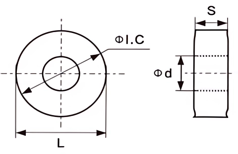
| Insert shape | Type | Dimension (mm) | Grade | |||||||||||||
|---|---|---|---|---|---|---|---|---|---|---|---|---|---|---|---|---|
| P | M | K | H | Cermet | ||||||||||||
| ΦI.C | L | S | Φd | TP15S | TP25S | TP25T | TP40S | TA20F | TA10A | TM20R | TK10R | TA05A | TMC20 | TMC35 | ||
 |
TRNMG120400 | 12.7 | 12.7 | 4.76 | 5.16 | ○ | ● | |||||||||
 |
TRCMX160600-PR8 | 16 | 16 | 6.35 | 5.5 | ○ | ● | |||||||||
| TRCMX200600-PR8 | 20 | 20 | 6.35 | 6.5 | ○ | ● | ||||||||||
| TRCMX250700-PR8 | 25 | 25 | 7.94 | 7.2 | ● | ○ | ||||||||||
| TRCMX320900-PR8 | 32 | 32 | 9.52 | 9.5 | ● | ○ | ||||||||||

| Insert shape | Type | Dimension (mm) | Grade | ||||||||||||||
|---|---|---|---|---|---|---|---|---|---|---|---|---|---|---|---|---|---|
| P | M | K | H | Cermet | |||||||||||||
| ΦI.C | L | S | Φd | Re | TP15S | TP15T | TP25S | TP25T | TA20F | TA10A | TM20R | TK10R | TA05A | TMC20 | TMC35 | ||
 |
TCCMT060204-HS2 | 6.35 | 6.4 | 2.38 | 2.8 | 0.4 | ◐ | ● | |||||||||
| TCCMT060208-HS2 | 6.35 | 6.4 | 2.38 | 2.8 | 0.8 | ◐ | ● | ||||||||||
| TCCMT09T304-HS2 | 9.525 | 9.7 | 3.97 | 4.4 | 0.4 | ◐ | ● | ||||||||||
| TCCMT09T308-HS2 | 9.525 | 9.7 | 3.97 | 4.4 | 0.8 | ◐ | ● | ||||||||||
| TCCMT120404-HS2 | 12.7 | 12.9 | 4.76 | 5.5 | 0.4 | ◐ | ● | ||||||||||
| TCCMT120408-HS2 | 12.7 | 12.9 | 4.76 | 5.5 | 0.8 | ◐ | ● | ||||||||||
 |
TCCMT060204-SM3 | 6.35 | 6.4 | 2.38 | 2.8 | 0.4 | ● | ◐ | |||||||||
| TCCMT060208-SM3 | 6.35 | 6.4 | 2.38 | 2.8 | 0.8 | ● | ◐ | ||||||||||
| TCCMT09T304-SM3 | 9.525 | 9.7 | 3.97 | 4.4 | 0.4 | ● | ◐ | ||||||||||
| TCCMT09T308-SM3 | 9.525 | 9.7 | 3.97 | 4.4 | 0.8 | ● | ◐ | ||||||||||
| TCCMT120404-SM3 | 12.7 | 12.9 | 4.76 | 5.5 | 0.4 | ● | ◐ | ||||||||||
| TCCMT120408-SM3 | 12.7 | 12.9 | 4.76 | 5.5 | 0.8 | ● | ◐ | ||||||||||
 |
TCCMT060204-PF3 | 6.35 | 6.4 | 2.38 | 2.8 | 0.4 | ● | ||||||||||
| TCCMT060208-PF3 | 6.35 | 6.4 | 2.38 | 2.8 | 0.8 | ● | |||||||||||
| TCCMT09T304-PF3 | 9.525 | 9.7 | 3.97 | 4.5 | 0.4 | ● | |||||||||||
| TCCMT09T308-PF3 | 9.525 | 9.7 | 3.97 | 4.5 | 0.8 | ● | |||||||||||
| TCCMT120404-PF3 | 12.7 | 12.9 | 4.76 | 5.5 | 0.4 | ● | |||||||||||
| TCCMT120408-PF3 | 12.7 | 12.9 | 4.76 | 5.5 | 0.8 | ● | |||||||||||
 |
TCCMT09T304-PM4 | 9.525 | 9.7 | 3.97 | 4.4 | 0.4 | ◐ | ● | ● | ● | |||||||
| TCCMT09T308-PM4 | 9.525 | 9.7 | 3.97 | 4.4 | 0.8 | ◐ | ● | ● | ● | ||||||||
| TCCMT120404-PM4 | 12.7 | 12.9 | 4.76 | 5.5 | 0.4 | ◐ | ● | ● | ● | ||||||||
| TCCMT120408-PM4 | 12.7 | 12.9 | 4.76 | 5.5 | 0.8 | ◐ | ● | ● | ● | ||||||||
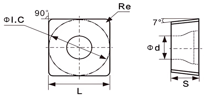
| Insert shape | Type | Dimension (mm) | Grade | ||||||||||||||
|---|---|---|---|---|---|---|---|---|---|---|---|---|---|---|---|---|---|
| P | M | K | H | Cermet | |||||||||||||
| ΦI.C | L | S | Φd | Re | TP15S | TP25S | TP25T | TP40S | TA20F | TA10A | TM20R | TK10R | TA05A | TMC20 | TMC35 | ||
 |
TSCMT09T304-HS2 | 9.525 | 9.525 | 3.97 | 4.4 | 0.4 | ◐ | ● | |||||||||
| TSCMT09T308-HS2 | 9.525 | 9.525 | 3.97 | 4.4 | 0.8 | ◐ | ● | ||||||||||
| TSCMT120404-HS2 | 12.7 | 12.7 | 4.76 | 5.56 | 0.4 | ◐ | ● | ||||||||||
| TSCMT120408-HS2 | 12.7 | 12.7 | 4.76 | 5.56 | 0.8 | ◐ | ● | ||||||||||
 |
TSCMT09T304-SM3 | 9.525 | 9.525 | 3.97 | 4.4 | 0.4 | ● | ◐ | |||||||||
| TSCMT09T308-SM3 | 9.525 | 9.525 | 3.97 | 4.4 | 0.8 | ● | ◐ | ||||||||||
| TSCMT120404-SM3 | 12.7 | 12.7 | 4.76 | 5.56 | 0.4 | ● | ◐ | ||||||||||
| TSCMT120408-SM3 | 12.7 | 12.7 | 4.76 | 5.56 | 0.8 | ● | ◐ | ||||||||||
 |
TSCMT09T304-PF3 | 9.525 | 9.525 | 3.97 | 4.4 | 0.4 | ● | ||||||||||
| TSCMT09T308-PF3 | 9.525 | 9.525 | 3.97 | 4.4 | 0.8 | ● | |||||||||||
| TSCMT120404-PF3 | 12.7 | 12.7 | 4.76 | 5.56 | 0.4 | ● | |||||||||||
| TSCMT120408-PF3 | 12.7 | 12.7 | 4.76 | 5.56 | 0.8 | ● | |||||||||||

| Insert shape | Type | Dimension (mm) | Grade | ||||||||||||||
|---|---|---|---|---|---|---|---|---|---|---|---|---|---|---|---|---|---|
| P | M | K | H | Cermet | |||||||||||||
| ΦI.C | L | S | Φd | Re | TP15S | TP25S | TP25T | TP40S | TA20F | TA10A | TM20R | TK10R | TA05A | TMC20 | TMC35 | ||
| TVBMT110304 | 6.35 | 11 | 3.18 | 2.8 | 0.4 | ◐ | ● | ||||||||||
| TVBMT110308 | 6.35 | 11 | 3.18 | 2.8 | 0.8 | ◐ | ● | ||||||||||
| TVBMT160404 | 9.525 | 16.5 | 4.76 | 4.4 | 0.4 | ◐ | ● | ||||||||||
| TVBMT160408 | 9.525 | 16.5 | 4.76 | 4.4 | 0.8 | ◐ | ● | ||||||||||
| TVBMT110304 | 6.35 | 11 | 3.18 | 2.8 | 0.4 | ● | ◐ | ||||||||||
| TVBMT110308 | 6.35 | 11 | 3.18 | 2.8 | 0.8 | ● | ◐ | ||||||||||
| TVBMT160404 | 9.525 | 16.5 | 4.76 | 4.4 | 0.4 | ● | ◐ | ||||||||||
| TVBMT160408 | 9.525 | 16.5 | 4.76 | 4.4 | 0.8 | ● | ◐ | ||||||||||
| TVBMT160404 | 9.525 | 16.5 | 4.76 | 4.4 | 0.4 | ● | ◐ | ||||||||||
| TVBMT160408 | 9.525 | 16.5 | 4.76 | 4.4 | 0.8 | ● | ◐ | ||||||||||
| TVBMT160404 | 9.525 | 16.5 | 4.76 | 4.4 | 0.4 | ● | ◐ | ||||||||||
| TVBMT160408 | 9.525 | 16.5 | 4.76 | 4.4 | 0.8 | ● | ◐ | ||||||||||
| TVBMT110304 | 6.35 | 11 | 3.18 | 2.8 | 0.4 | ◐ | ● | ||||||||||
| TVBMT110308 | 6.35 | 11 | 3.18 | 2.8 | 0.8 | ◐ | ● | ||||||||||
| TVBMT160404 | 9.525 | 16.5 | 4.76 | 4.4 | 0.4 | ◐ | ● | ||||||||||
| TVBMT160408 | 9.525 | 16.5 | 4.76 | 4.4 | 0.8 | ◐ | ● | ||||||||||
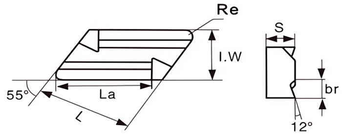
| Insert shape | Type | Dimension (mm) | Grade | |||||||||||||||
|---|---|---|---|---|---|---|---|---|---|---|---|---|---|---|---|---|---|---|
| P | M | K | H | Cermet | ||||||||||||||
| La | L | I.W | S | br | Re | TP15S | TP25S | TP25T | TP40S | TA20F | TA10A | TM20R | TK10R | TA05A | TMC20 | TMC35 | ||
 |
TKNUX160405-L11 | 16 | 16.15 | 9.525 | 4.76 | 2.2 | 0.5 | ● | ● | |||||||||
| TKNUX160410-L11 | 16 | 16.15 | 9.525 | 4.76 | 2.2 | 1 | ● | ● | ||||||||||
| TKNUX160405-R11 | 16 | 16.15 | 9.525 | 4.76 | 2.2 | 0.5 | ● | ● | ||||||||||
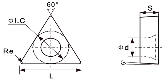
| Insert shape | Type | Dimension (mm) | Grade | ||||||||||||||
|---|---|---|---|---|---|---|---|---|---|---|---|---|---|---|---|---|---|
| P | M | K | H | Cermet | |||||||||||||
| ΦI.C | L | S | Φd | Re | TP15S | TP25S | TP25T | TP40S | TA20F | TA10A | TM20R | TK10R | TA05A | TMC20 | TMC35 | ||
 |
TTBGT060102L-W | 3.97 | 6.4 | 1.59 | 2.2 | 0.2 | ◐ | ● | |||||||||
| TTBGT060104L-W | 3.97 | 6.4 | 1.59 | 2.2 | 0.4 | ◐ | ● | ||||||||||
 |
TTPGT080202L-W | 4.76 | 8.2 | 2.38 | 2.4 | 0.2 | ◐ | ● | |||||||||
| TTPGT080204L-W | 4.76 | 8.2 | 2.38 | 2.4 | 0.4 | ◐ | ● | ||||||||||
| TTPGT090202L-W | 5.56 | 9.6 | 2.38 | 2.8 | 0.2 | ◐ | ● | ||||||||||
| TTPGT090204L-W | 5.56 | 9.6 | 2.38 | 2.8 | 0.4 | ◐ | ● | ||||||||||
| TTPGT110302L-W | 6.35 | 11 | 3.18 | 3.18 | 0.2 | ◐ | ● | ||||||||||
| TTPGT110304L-W | 6.35 | 11 | 3.18 | 3.18 | 0.4 | ◐ | ● | ||||||||||
 |
TTCGT110202L-W | 6.35 | 11 | 2.38 | 3.18 | 0.2 | ◐ | ● | |||||||||
| TTCGT110204L-W | 6.35 | 11 | 2.38 | 3.18 | 0.4 | ◐ | ● | ||||||||||
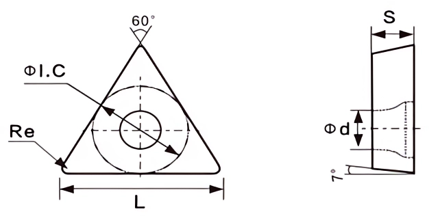
| Insert shape | Type | Dimension (mm) | Grade | ||||||||||||||
|---|---|---|---|---|---|---|---|---|---|---|---|---|---|---|---|---|---|
| P | M | K | H | Cermet | |||||||||||||
| ΦI.C | L | S | Φd | Re | TP15S | TP25S | TP25T | TP40S | TA20F | TA10A | TM20R | TK10R | TA05A | TMC20 | TMC35 | ||
 |
TTCMT090204-HS2 | 5.56 | 9.6 | 2.38 | 2.5 | 0.4 | ◐ | ● | |||||||||
| TTCMT090208-HS2 | 5.56 | 9.6 | 2.38 | 2.5 | 0.8 | ◐ | ● | ||||||||||
| TTCMT110204-HS2 | 6.35 | 11 | 2.38 | 2.8 | 0.4 | ◐ | ● | ||||||||||
| TTCMT110208-HS2 | 6.35 | 11 | 2.38 | 2.8 | 0.8 | ◐ | ● | ||||||||||
| TTCMT16T304-HS2 | 9.525 | 16.5 | 3.97 | 4.4 | 0.4 | ◐ | ● | ||||||||||
| TTCMT16T308-HS2 | 9.525 | 16.5 | 3.97 | 4.4 | 0.8 | ◐ | ● | ||||||||||
 |
TTCMT090204-SM3 | 5.56 | 9.6 | 2.38 | 2.5 | 0.4 | ● | ◐ | |||||||||
| TTCMT090208-SM3 | 5.56 | 9.6 | 2.38 | 2.5 | 0.8 | ● | ◐ | ||||||||||
| TTCMT110204-SM3 | 6.35 | 11 | 2.38 | 2.8 | 0.4 | ● | ◐ | ||||||||||
| TTCMT110208-SM3 | 6.35 | 11 | 2.38 | 2.8 | 0.8 | ● | ◐ | ||||||||||
| TTCMT16T304-SM3 | 9.525 | 16.5 | 3.97 | 4.4 | 0.4 | ● | ◐ | ||||||||||
| TTCMT16T308-SM3 | 9.525 | 16.5 | 3.97 | 4.4 | 0.8 | ● | ◐ | ||||||||||
 |
TTCMT090204-PF3 | 5.56 | 9.6 | 2.38 | 2.5 | 0.4 | ◐ | ○ | ● | ||||||||
| TTCMT090208-PF3 | 5.56 | 9.6 | 2.38 | 2.5 | 0.8 | ◐ | ○ | ● | |||||||||
| TTCMT110204-PF3 | 6.35 | 11 | 2.38 | 2.8 | 0.4 | ◐ | ○ | ● | |||||||||
| TTCMT110208-PF3 | 6.35 | 11 | 2.38 | 2.8 | 0.8 | ◐ | ○ | ● | |||||||||
| TTCMT16T304-PF3 | 9.525 | 16.5 | 3.97 | 4.4 | 0.4 | ◐ | ○ | ● | |||||||||
| TTCMT16T308-PF3 | 9.525 | 16.5 | 3.97 | 4.4 | 0.8 | ◐ | ○ | ● | |||||||||
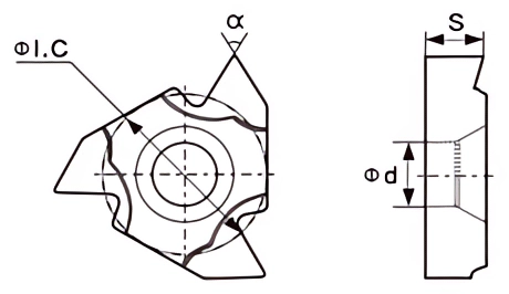
| Insert shape | Type | Dimension (mm) | Grade | ||||||||||||||
|---|---|---|---|---|---|---|---|---|---|---|---|---|---|---|---|---|---|
| P | M | K | H | Cermet | |||||||||||||
| Teeth number | ΦI.C | S | Φd | α° | TP15S | TP25S | TP25T | TP40S | TA20F | TA10A | TM20R | TK10R | TA05A | TMC20 | TMC35 | ||
 |
TT161R11WS | 11 | 9.525 | 3.52 | 4 | 55 | ● | ◐ | |||||||||
| TT161R14WS | 14 | 9.525 | 3.52 | 4 | 55 | ● | ◐ | ||||||||||
| TT16ER11WS | 11 | 9.525 | 3.52 | 4 | 55 | ● | ◐ | ||||||||||
| TT16ER14WS | 14 | 9.525 | 3.52 | 4 | 55 | ● | ◐ | ||||||||||
 |
TT161R1.5ISO | 1.5 | 9.525 | 3.52 | 4 | 55 | ● | ◐ | |||||||||
| TT161R2.0ISO | 2 | 9.525 | 3.52 | 4 | 55 | ● | ◐ | ||||||||||
| TT16ER1.5ISO | 1.5 | 9.525 | 3.52 | 4 | 55 | ● | ◐ | ||||||||||
| TT16ER2.0ISO | 2 | 9.525 | 3.52 | 4 | 55 | ● | ◐ | ||||||||||

| Insert shape | Type | Dimension (mm) | Grade | ||||||||||||||
|---|---|---|---|---|---|---|---|---|---|---|---|---|---|---|---|---|---|
| P | M | K | H | Cermet | |||||||||||||
| b | Re | L | d | t | TP15S | TP25S | TP25T | TP40S | TA20F | TA10A | TM20R | TK10R | TA05A | TMC20 | TMC35 | ||
| TJSMN150-02-N | 1.5 | 0.15 | 16 | 1.2 | 3.5 | ● | ● | ||||||||||
| TJSMN200-02-N | 2 | 0.2 | 16 | 1.6 | 3.5 | ● | ● | ||||||||||
| TJSMN250-02-N | 2.5 | 0.2 | 18.5 | 2 | 3.85 | ● | ● | ||||||||||
| TJSMN300-04-C | 3 | 0.4 | 21 | 2.35 | 4.8 | ● | ● | ||||||||||
| TJSMN400-04-C | 4 | 0.4 | 21 | 3.3 | 4.8 | ● | ● | ||||||||||
| TJSMN500-08-C | 5 | 0.8 | 26 | 4.1 | 5.8 | ● | ● | ||||||||||
| TJSMN600-08-C | 6 | 0.8 | 26 | 4.1 | 5.8 | ● | ● | ||||||||||
| TJRMN200-10-C | 2 | 1 | 16 | 1.5 | 3.5 | ● | ● | ||||||||||
| TJRMN300-15-C | 3 | 1.5 | 21 | 2.35 | 4.8 | ● | ● | ||||||||||
| TJRMN400-20-C | 4 | 2 | 21 | 3.3 | 4.8 | ● | ● | ||||||||||
| TJRMN500-25-C | 5 | 2.5 | 26 | 4.1 | 5.8 | ● | ● | ||||||||||
| TJRMN600-30-C | 6 | 3 | 26 | 4.1 | 5.8 | ● | ● | ||||||||||
| TJRMN800-40-C | 8 | 4 | 31 | 4.1 | 6.5 | ● | ● | ||||||||||
Milling Inserts Data
Milling Carbide Insert Description
Milling inserts, also known as milling cutters or milling tips, are cutting tools used in milling operations to remove material from a workpiece. These inserts are typically made of hard carbide material and are designed to be mounted on a milling cutter or milling machine.
Milling inserts come in a variety of shapes, sizes, and geometries to suit different milling applications. They feature multiple cutting edges or flutes that facilitate efficient material removal and precise milling operations. The geometry and cutting edge design of the insert are optimized to achieve specific milling tasks, such as roughing, finishing, contouring, or slotting.
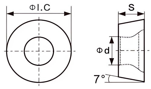
| Insert shape | Type | Dimension (mm) | Grade | |||||||||
|---|---|---|---|---|---|---|---|---|---|---|---|---|
| P M K | Cermet | |||||||||||
| ΦI.C | S | Φd | TA05A | TA10A | TA20F | TA20H | TM30R | TK10R | TMC20 | TMC35 | ||
 |
TRCKT10T3MO-DS3 | 10 | 3.97 | 4.4 | ● | |||||||
 |
TRCKT1204MO-DS3 | 12 | 4.76 | 4 | ● | |||||||
 |
TRCKT1606MO-BR8 | 16 | 6.35 | 5.5 | ● | ◐ | ○ | |||||
 |
TRCMX1204MO | 12 | 4.76 | 4.2 | ● | ◐ | ○ | |||||
| TRCMX1606MO | 16 | 6.35 | 5.2 | ● | ◐ | ○ | ||||||
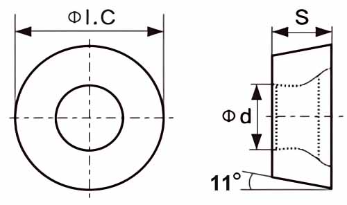
| Insert shape | Type | Dimension (mm) | Grade | |||||||||
|---|---|---|---|---|---|---|---|---|---|---|---|---|
| P M K | Cermet | |||||||||||
| ΦI.C | S | Φd | TA05A | TA10A | TA20F | TA20H | TM30R | TK10R | TMC20 | TMC35 | ||
 |
TRPMW08T2MOT | 8 | 2.8 | 3.3 | ◐ | ● | ○ | |||||
| TRPMW1003MO | 10 | 3.18 | 4.5 | ◐ | ● | ○ | ||||||
| TRPMW10T3MO | 10 | 3.97 | 4.6 | ◐ | ● | ○ | ||||||
| TRPMW1204MO | 12 | 4.76 | 4.4 | ◐ | ● | ○ | ||||||
 |
TRPMT08T2MO-JS | 8 | 2.58 | 3.3 | ◐ | ● | ||||||
| TRPMT10T3MO-JS | 10 | 3.97 | 4.4 | ◐ | ● | |||||||
| TRPMT1204MO-JS | 12 | 4.76 | 4.3 | ◐ | ● | |||||||
 |
TRPMT1204MO-DL | 12 | 4.76 | 4.4 | ◐ | ● | ||||||
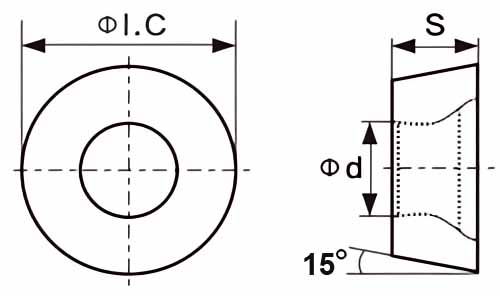
| Insert shape | Type | Dimension (mm) | Grade | |||||||||
|---|---|---|---|---|---|---|---|---|---|---|---|---|
| P M K | Cermet | |||||||||||
| ΦI.C | S | Φd | TA05A | TA10A | TA20F | TA20H | TM30R | TK10R | TMC20 | TMC35 | ||
 |
TRDMW1204MO-NR8 | 12 | 4.76 | 4.4 | ◐ | ● | ||||||
| TRDMW1605MO-NR8 | 16 | 5.56 | 5.5 | ◐ | ● | |||||||
 |
TRDMW1204MO | 12 | 4.76 | 4.4 | ● | ◐ | ||||||
| TRDMW1604MO | 16 | 4.76 | 5 | ● | ◐ | |||||||
| TRDMW1605MO | 16 | 5.56 | 5.5 | ● | ◐ | |||||||
 |
TRDMT0802MO-SN | 8 | 2.48 | 3.4 | ● | ◐ | ||||||
| TRDMT10T3MO-SN | 10 | 3.97 | 4.5 | ● | ◐ | |||||||
| TRDMT1204MO-SN | 12 | 4.76 | 4.4 | ● | ◐ | |||||||
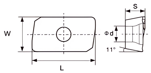
| Insert shape | Type | Dimension (mm) | Grade | |||||||||||
|---|---|---|---|---|---|---|---|---|---|---|---|---|---|---|
| P M K | Cermet | |||||||||||||
| L | S | W | Φd | Re | TA05A | TA10A | TA20F | TA20H | TM30R | TK10R | TMC20 | TMC35 | ||
 |
TAPMT1135PDER-M2 | 11.32 | 3.5 | 6.19 | 2.85 | 0.8 | ◐ | ● | ● | |||||
| TAPMT1604PDER-M2 | 17.21 | 4.76 | 9.29 | 4.48 | 0.8 | ◐ | ● | ● | ||||||
 |
TAPMT1135PDER-H2 | 11.22 | 3.5 | 6.2 | 2.8 | 0.8 | ◐ | ● | ● | |||||
| TAPMT1604PDER-H2 | 17.25 | 4.76 | 9.26 | 4.4 | 0.8 | ◐ | ● | ● | ||||||
 |
TAPMT1135PDER-DL | 11.28 | 3.6 | 6.22 | 2.8 | 0.8 | ◐ | ● | ||||||
| TAPMT1604PDER-DL | 17.37 | 5.33 | 9.32 | 4.5 | 0.8 | ◐ | ● | |||||||
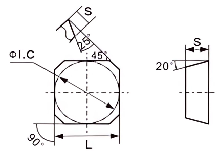
| Insert shape | Type | Dimension (mm) | Grade | |||||||||
|---|---|---|---|---|---|---|---|---|---|---|---|---|
| P M K | Cermet | |||||||||||
| ΦI.C | L | S | TA05A | TA10A | TA20F | TA20H | TM30R | TK10R | TMC20 | TMC35 | ||
 |
TSEEN1203AFTN | 12.7 | 12.7 | 3.18 | ◐ | ● | ||||||
| TSEEN1504AFTN | 15.875 | 15.875 | 4.76 | ◐ | ● | |||||||
| TSPKN1203ERER | 12.7 | 12.7 | 3.18 | ● | ◐ | ● | ||||||
| TSPKN1203EDEL | 12.7 | 12.7 | 3.18 | ● | ||||||||
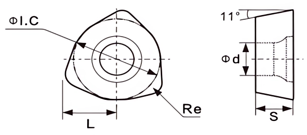
| Insert shape | Type | Dimension (mm) | Grade | |||||||||||
|---|---|---|---|---|---|---|---|---|---|---|---|---|---|---|
| P M K | Cermet | |||||||||||||
| ΦI.C | S | L | Φd | Re | TA05A | TA10A | TA20F | TA20H | TM30R | TK10R | TMC20 | TMC35 | ||
 |
TWPGT080615ZSR | 12.85 | 6.35 | 5.8 | 5.5 | 1.5 | ● | ◐ | ||||||

| Insert shape | Type | Dimension (mm) | Grade | ||||||||||
|---|---|---|---|---|---|---|---|---|---|---|---|---|---|
| P M K | Cermet | ||||||||||||
| ΦI.C | S | B | Re | TA05A | TA10A | TA20F | TA20H | TM30R | TK10R | TMC20 | TMC35 | ||
 |
TWDMW06T320ZTR | 10 | 3.97 | 1.2 | 2 | ● | ○ | ||||||
| TWDMW080520ZTR | 13 | 5.5 | 1.5 | 2 | ● | ○ | |||||||
| TWDMW10X620ZTR | 13 | 6 | 1.2 | 2 | ● | ○ | |||||||

| Insert shape | Type | Dimension (mm) | Grade | ||||||||||
|---|---|---|---|---|---|---|---|---|---|---|---|---|---|
| P M K | Cermet | ||||||||||||
| ΦI.C | S | B | Re | TA05A | TA10A | TA20F | TA20H | TM30R | TK10R | TMC20 | TMC35 | ||
 |
TJDMW09T320SR | 9.53 | 3.97 | 1.8 | 2 | ◐ | ● | ○ | |||||
| TJDMW120420SR | 13 | 5.5 | 1.5 | 2 | ◐ | ● | ○ | ||||||
| TJDMW140520SR | 13 | 6 | 1.2 | 2 | ◐ | ● | ○ | ||||||

| Insert shape | Type | Dimension (mm) | Grade | |||||||||||
|---|---|---|---|---|---|---|---|---|---|---|---|---|---|---|
| P M K | Cermet | |||||||||||||
| L | S | W | Φd | Re | TA05A | TA10A | TA20F | TA20H | TM30R | TK10R | TMC20 | TMC35 | ||
 |
TLNMU0303ER-GM3 | 11.9 | 3.75 | 6 | 2.85 | 1.2 | ● | ○ | ||||||
| TLNMU0303ER-GS3 | 11.9 | 3.75 | 6 | 2.85 | 1.2 | ● | ○ | |||||||
 |
TLOGU030310ER-GM3 | 12 | 3.96 | 6.22 | 3.45 | 1 | ● | ○ | ||||||
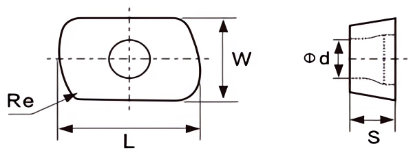
| Insert shape | Type | Dimension (mm) | Grade | |||||||||||
|---|---|---|---|---|---|---|---|---|---|---|---|---|---|---|
| P M K | Cermet | |||||||||||||
| L | S | W | Φd | Re | TA05A | TA10A | TA20F | TA20H | TM30R | TK10R | TMC20 | TMC35 | ||
 |
TEPMT0603SN-R8 | 10 | 3.18 | 6.35 | 2.8 | 8 | ○ | ◐ | ● | |||||
| TEPNW0603SN-R8 | 10 | 3.18 | 6.35 | 2.8 | 8 | ○ | ◐ | ● | ||||||

| Insert shape | Type | Dimension (mm) | Grade | |||||||||||
|---|---|---|---|---|---|---|---|---|---|---|---|---|---|---|
| P M K | Cermet | |||||||||||||
| L | S | W | Φd | Re | TA05A | TA10A | TA20F | TA20H | TM30R | TK10R | TMC20 | TMC35 | ||
 |
TLPGT010210ER-GM3 | 6.26 | 2.19 | 4.19 | 2.1 | 1 | ◐ | ● | ||||||
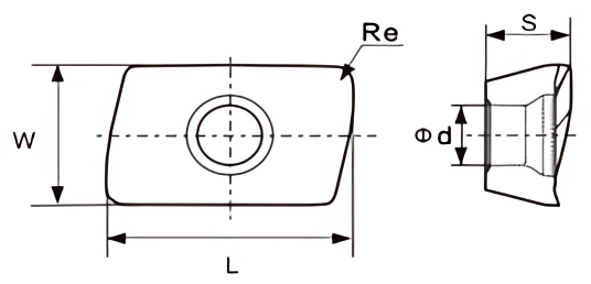
| Insert shape | Type | Dimension (mm) | Grade | |||||||||||
|---|---|---|---|---|---|---|---|---|---|---|---|---|---|---|
| P M K | Cermet | |||||||||||||
| L | S | W | Φd | Re | TA05A | TA10A | TA20F | TA20H | TM30R | TK10R | TMC20 | TMC35 | ||
 |
TXOMX10T308SR-M2 | 10.2 | 3.85 | 6.9 | 2.96 | 0.8 | ○ | ◐ | ● | |||||
| TXOMX120418SR-M3 | 12.7 | 5.07 | 8.2 | 3.85 | 0.8 | ○ | ◐ | ● | ||||||
| TXOMX120412SR-M1 | 12.7 | 5.05 | 8.2 | 3.9 | 1.2 | ○ | ◐ | ● | ||||||
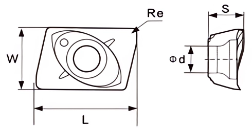
| Insert shape | Type | Dimension (mm) | Grade | |||||||||||
|---|---|---|---|---|---|---|---|---|---|---|---|---|---|---|
| P M K | Cermet | |||||||||||||
| L | S | W | Φd | Re | TA05A | TA10A | TA20F | TA20H | TM30R | TK10R | TMC20 | TMC35 | ||
 |
TJDMT070204R | 6.48 | 2.45 | 4.25 | 1.9 | 0.4 | ● | ◐ | ○ | |||||
| TJDMT070208R | 6.48 | 2.45 | 4.25 | 1.9 | 0.8 | ● | ◐ | ○ | ||||||
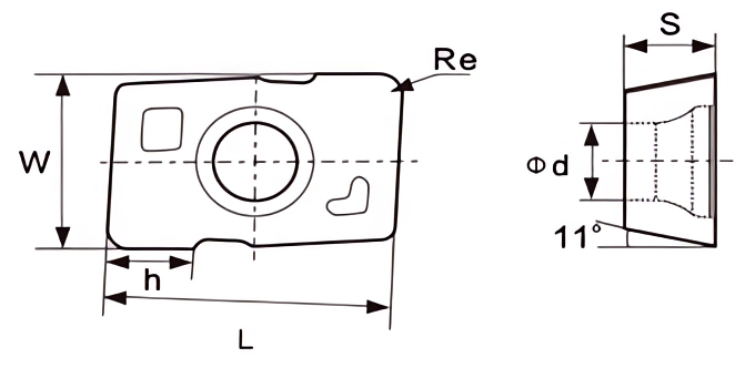
| Insert shape | Type | Dimension (mm) | Grade | |||||||||||
|---|---|---|---|---|---|---|---|---|---|---|---|---|---|---|
| P M K | Cermet | |||||||||||||
| L | S | W | Φd | Re | TA05A | TA10A | TA20F | TA20H | TM30R | TK10R | TMC20 | TMC35 | ||
 |
TMPHW060308ZEL | 10 | 3.18 | 6.34 | 2.9 | 0.8 | ● | ◐ | ○ | |||||
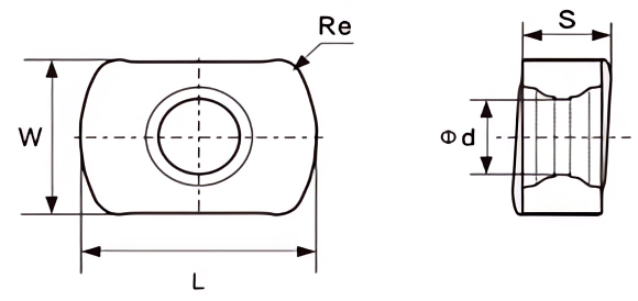
| Insert shape | Type | Dimension (mm) | Grade | |||||||||||
|---|---|---|---|---|---|---|---|---|---|---|---|---|---|---|
| P M K | Cermet | |||||||||||||
| L | S | W | Φd | Re | TA05A | TA10A | TA20F | TA20H | TM30R | TK10R | TMC20 | TMC35 | ||
 |
TBNMX0603R-M | 9 | 3.73 | 6.39 | 3.1 | 1 | ◐ | ● | ○ | |||||
| TBNMX0904R-M | 11.95 | 4.39 | 9.15 | 4.1 | 1.35 | ◐ | ● | ○ | ||||||

| Insert shape | Type | Dimension (mm) | Grade | |||||||||||
|---|---|---|---|---|---|---|---|---|---|---|---|---|---|---|
| P M K | Cermet | |||||||||||||
| ΦI.C | S | L | Φd | Re | TA05A | TA10A | TA20F | TA20H | TM30R | TK10R | TMC20 | TMC35 | ||
 |
TSEMT13T3AGSN-GM3 | 13.4 | 3.97 | 13.4 | 4.4 | 1 | ◐ | ● | ○ | |||||
 |
TSEKT1204AFTN-DR7 | 12.7 | 4.76 | 12.7 | 5.5 | 0.8 | ◐ | ● | ○ | |||||

| Insert shape | Type | Dimension (mm) | Grade | |||||||||||
|---|---|---|---|---|---|---|---|---|---|---|---|---|---|---|
| P M K | Cermet | |||||||||||||
| ΦI.C | S | L | Φd | Re | TA05A | TA10A | TA20F | TA20H | TM30R | TK10R | TMC20 | TMC35 | ||
 |
TSEMR1203AFTN | 12.7 | 3.18 | 12.7 | 2.3 | 1.6 | ● | ○ | ||||||
| TSEMR1504AFTN | 15.875 | 4.76 | 15.875 | 3.2 | 1.6 | ● | ○ | |||||||
| TSEKR1203AFTN | 12.7 | 3.18 | 12.7 | 2.3 | 1.6 | ● | ○ | |||||||
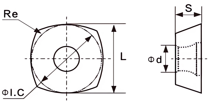
| Insert shape | Type | Dimension (mm) | Grade | |||||||||||
|---|---|---|---|---|---|---|---|---|---|---|---|---|---|---|
| P M K | Cermet | |||||||||||||
| ΦI.C | S | L | Φd | Re | TA05A | TA10A | TA20F | TA20H | TM30R | TK10R | TMC20 | TMC35 | ||
 |
TSDMT09T3 | 12.66 | 5.54 | 15.3 | 4.4 | 1.2 | ◐ | ● | ○ | |||||
| TSDMT1204 | 12.7 | 4.76 | 12.7 | 4.4 | 1.2 | ◐ | ● | ○ | ||||||
| TSDMT120512-GM3 | 12.66 | 5.54 | 12.66 | 4.4 | 1.2 | ◐ | ● | ○ | ||||||
| TSDMT150512-GM3 | 15.875 | 5.56 | 15.875 | 5.5 | 1.2 | ◐ | ● | ○ | ||||||
| TSDMT1205ZDTN-R15 | 12.7 | 5.54 | 12.7 | 4.6 | 2.8 | ● | ◐ | ○ | ||||||
| TSDMT1505ZDTN-R15 | 15.875 | 5.56 | 15.875 | 5.5 | 0.8 | ● | ◐ | ○ | ||||||
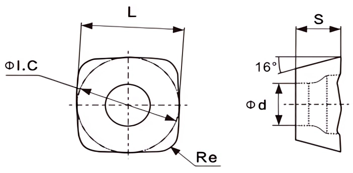
| Insert shape | Type | Dimension (mm) | Grade | |||||||||||
|---|---|---|---|---|---|---|---|---|---|---|---|---|---|---|
| P M K | Cermet | |||||||||||||
| ΦI.C | S | L | Φd | Re | TA05A | TA10A | TA20F | TA20H | TM30R | TK10R | TMC20 | TMC35 | ||
 |
TPNMU0905XNER-GM3 | 13.4 | 6.19 | 9.3 | 4.64 | 0.8 | ◐ | ● | ○ | |||||
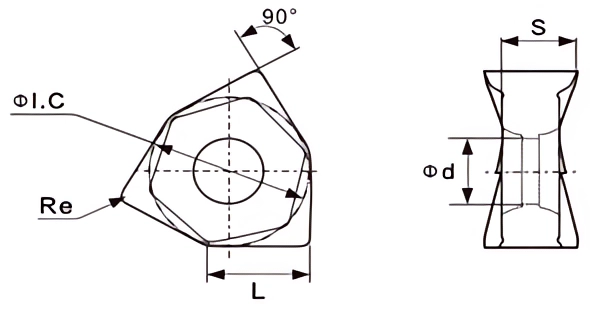
| Insert shape | Type | Dimension (mm) | Grade | |||||||||||
|---|---|---|---|---|---|---|---|---|---|---|---|---|---|---|
| P M K | Cermet | |||||||||||||
| ΦI.C | S | L | Φd | Re | TA05A | TA10A | TA20F | TA20H | TM30R | TK10R | TMC20 | TMC35 | ||
 |
TWNMU080608EN-GM3 | 14.02 | 6.55 | 8.87 | 6.2 | 0.8 | ● | ○ | ● | |||||
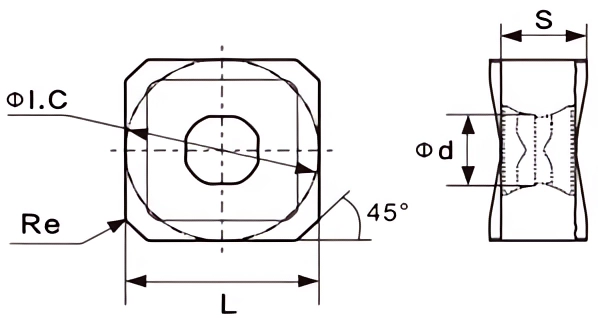
| Insert shape | Type | Dimension (mm) | Grade | |||||||||||
|---|---|---|---|---|---|---|---|---|---|---|---|---|---|---|
| P M K | Cermet | |||||||||||||
| ΦI.C | S | L | Φd | Re | TA05A | TA10A | TA20F | TA20H | TM30R | TK10R | TMC20 | TMC35 | ||
 |
TSNMX1306ENTN-M | 13.5 | 6.8 | 13.5 | 5.4 | 0.4 | ● | ◐ | ||||||
| TSNGX1306ANTN-M | 13.5 | 5.97 | 13.5 | 5.4 | 0.4 | ● | ◐ | |||||||
 |
TSNMX120512-F27 | 12.7 | 5.62 | 12.7 | 6 | 1.2 | ● | ◐ | ||||||
| TSNMX1205ANN-F57 | 12.7 | 5.51 | 12.7 | 6 | 0.8 | ● | ◐ | |||||||

| Insert shape | Type | Dimension (mm) | Grade | |||||||||||
|---|---|---|---|---|---|---|---|---|---|---|---|---|---|---|
| P M K | Cermet | |||||||||||||
| ΦI.C | S | L | Φd | Re | TA05A | TA10A | TA20F | TA20H | TM30R | TK10R | TMC20 | TMC35 | ||
 |
TONMU050505-TN | 13 | 5.5 | 3.5 | 5 | 0.5 | ● | ◐ | ||||||
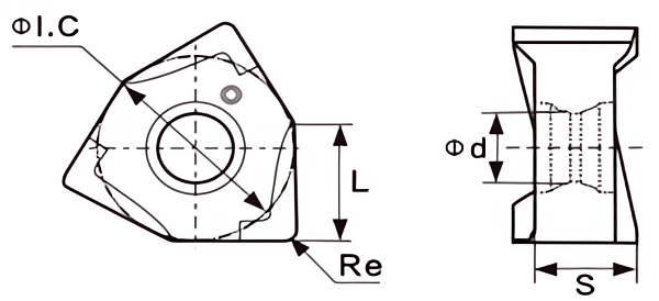
| Insert shape | Type | Dimension (mm) | Grade | |||||||||||
|---|---|---|---|---|---|---|---|---|---|---|---|---|---|---|
| P M K | Cermet | |||||||||||||
| ΦI.C | S | L | Φd | Re | TA05A | TA10A | TA20F | TA20H | TM30R | TK10R | TMC20 | TMC35 | ||
 |
TXNEX040304TR-EM3 | 6.71 | 3.29 | 4.3 | 3.1 | 0.4 | ● | ◐ | ||||||
| TXNEX040308TR-EM3 | 6.71 | 3.29 | 4.3 | 3.1 | 0.8 | |||||||||
| TXNEX080608TR-NR8 | 12.48 | 6.45 | 8 | 4.65 | 0.8 | ● | ◐ | |||||||
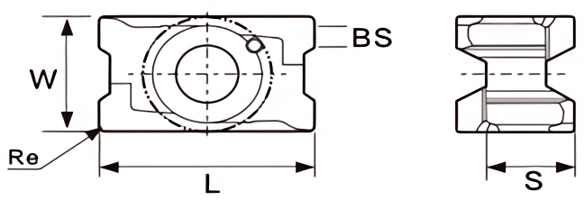
| Insert shape | Type | Dimension (mm) | Grade | |||||||||||
|---|---|---|---|---|---|---|---|---|---|---|---|---|---|---|
| P M K | Cermet | |||||||||||||
| L | S | W | BS | Re | TA05A | TA10A | TA20F | TA20H | TM30R | TK10R | TMC20 | TMC35 | ||
 |
TLNPU110408SR-NR8 | 12.1 | 4.83 | 6.6 | 0.9 | 0.8 | ○ | ● | ◐ | |||||
| TLNPU15T608SR-NR8 | 16.9 | 6.96 | 10 | 1.8 | 0.8 | ○ | ● | ◐ | ||||||
 |
TLNPU110408ER-DR7 | 12.16 | 4.83 | 6.6 | 1 | 0.8 | ○ | ● | ◐ | |||||
| TLNPU15T608ER-DR7 | 17.01 | 6.96 | 10 | 1.8 | 0.8 | ○ | ● | ◐ | ||||||
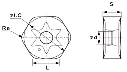
| Insert shape | Type | Dimension (mm) | Grade | |||||||||||
|---|---|---|---|---|---|---|---|---|---|---|---|---|---|---|
| P M K | Cermet | |||||||||||||
| ΦI.C | S | L | Φd | Re | TA05A | TA10A | TA20F | TA20H | TM30R | TK10R | TMC20 | TMC35 | ||
 |
THNGX0906ANSN-GM3 | 16.5 | 6.35 | 9.1 | 4.9 | 1 | ● | ◐ | ○ | |||||
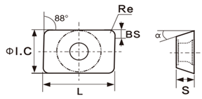
| Insert shape | Type | Dimension (mm) | Grade | |||||||||||
|---|---|---|---|---|---|---|---|---|---|---|---|---|---|---|
| P M K | Cermet | |||||||||||||
| ΦI.C | S | L | BS | Re | TA05A | TA10A | TA20F | TA20H | TM30R | TK10R | TMC20 | TMC35 | ||
 |
TLPMT150412 | 12.7 | 4.76 | 15.88 | 1.6 | 1.2 | ◐ | ● | ||||||
| TLPMT150612 | 12.7 | 6.35 | 15.88 | / | 1.2 | ◐ | ● | |||||||
Hole Machining Inserts
Hole Machining Inserts Description
Hole machining inserts, also known as drill inserts or drilling inserts, are cutting tools used in machining operations to create holes in various materials. These inserts are typically used with drilling tools such as drills, boring bars, or milling machines to remove material and produce holes with precision.
The main purpose of hole machining inserts is to provide a cutting edge that can efficiently cut through the workpiece material to form a hole. These inserts are typically made from durable and wear-resistant materials such as carbide, cermet, or high-speed steel (HSS). The choice of material depends on the specific machining application, material being machined, and desired cutting performance.
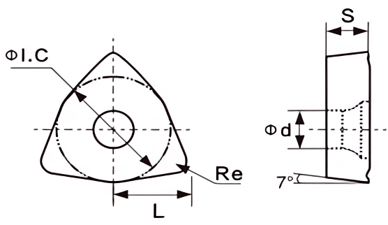
| Insert shape | Type | Dimension (mm) | Grade | |||||||||||
|---|---|---|---|---|---|---|---|---|---|---|---|---|---|---|
| P M K | Cermet | |||||||||||||
| ΦI.C | S | L | Φd | Re | TA05A | TA10A | TA20F | TA20H | TM30R | TK10R | TMC20 | TMC35 | ||
 |
TWCMX030208-EN | 5.56 | 2.38 | 3.8 | 2.8 | 0.8 | ◐ | ● | ||||||
| TWCMX040208-EN | 6.35 | 2.38 | 4.3 | 3.1 | 0.8 | ◐ | ● | |||||||
| TWCMT050308-EN | 7.94 | 3.18 | 5.5 | 3.4 | 0.8 | ◐ | ● | |||||||
| TWCMT06T308-EN | 9.525 | 3.97 | 6.5 | 3.8 | 0.8 | ◐ | ● | |||||||
| TWCMT080412-EN | 12.7 | 4.76 | 8.7 | 4.4 | 1.2 | ◐ | ● | |||||||

| Insert shape | Type | Dimension (mm) | Grade | |||||||||||
|---|---|---|---|---|---|---|---|---|---|---|---|---|---|---|
| P M K | Cermet | |||||||||||||
| ΦI.C | S | L | Φd | Re | TA05A | TA10A | TA20F | TA20H | TM30R | TK10R | TMC20 | TMC35 | ||
 |
TTPMT16T312R-22 | 9.525 | 3.97 | 16.5 | 3.4 | 1.2 | ● | ○ | ||||||
| TTPMT220612R-22 | 12.7 | 6.35 | 22 | 4.4 | 1.2 | ● | ○ | |||||||
 |
TTPMT16T312R-23 | 9.525 | 3.97 | 16.5 | 3.4 | 1.2 | ● | ○ | ||||||
| TTPMT220612R-23 | 12.7 | 6.35 | 22 | 4.4 | 1.2 | ● | ○ | |||||||

| Insert shape | Type | Dimension (mm) | Grade | |||||||||||
|---|---|---|---|---|---|---|---|---|---|---|---|---|---|---|
| P M K | Cermet | |||||||||||||
| ΦI.C | S | L | Φd | Re | TA05A | TA10A | TA20F | TA20H | TM30R | TK10R | TMC20 | TMC35 | ||
 |
TTPMX140308R-G | 8.45 | 3.52 | 8.3 | 2.8 | 0.8 | ● | ◐ | ||||||
| TTPMX170408R-G | 10.3 | 4.04 | 9.6 | 3.9 | 0.8 | ● | ◐ | |||||||
| TTPMX240512R-G | 14.2 | 5.5 | 13.9 | 4.4 | 1.2 | ● | ◐ | |||||||
| TTPMX280716R-G | 17 | 7.6 | 16.1 | 5.5 | 1.6 | ● | ◐ | |||||||
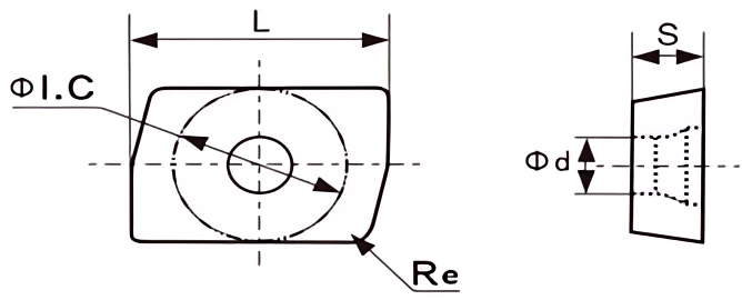
| Insert shape | Type | Dimension (mm) | Grade | |||||||||||
|---|---|---|---|---|---|---|---|---|---|---|---|---|---|---|
| P M K | Cermet | |||||||||||||
| ΦI.C | L | S | Φd | Re | TA05A | TA10A | TA20F | TA20H | TM30R | TK10R | TMC20 | TMC35 | ||
 |
R424.9-13T308-22 | 10 | 14.6 | 3.96 | 3.4 | 0.8 | ● | ○ | ||||||
| R424.9-180608-22 | 11.5 | 20.4 | 6.35 | 4.5 | 0.8 | ● | ○ | |||||||
 |
R424.9-13T308-23 | 10 | 14.6 | 3.96 | 3.4 | 0.8 | ● | ○ | ||||||
| R424.9-180608-23 | 11.5 | 20.4 | 6.35 | 4.5 | 0.8 | ● | ○ | |||||||
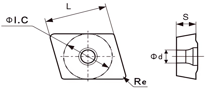
| Insert shape | Type | Dimension (mm) | Grade | |||||||||||
|---|---|---|---|---|---|---|---|---|---|---|---|---|---|---|
| P M K | Cermet | |||||||||||||
| ΦI.C | L | S | Φd | Re | TA05A | TA10A | TA20F | TA20H | TM30R | TK10R | TMC20 | TMC35 | ||
 |
TR800.24LH-06T308M-CG | 9.87 | 6.35 | 3.97 | 2.8 | 0.8 | ● | |||||||
| TR800.24LH-08T308M-CG | 9.87 | 7.94 | 3.97 | 2.8 | 0.8 | ● | ||||||||
| TR800.24LH-10T308M-CG | 9.87 | 9.53 | 3.97 | 2.8 | 0.8 | ● | ||||||||
| TR800.24LH-12T308M-CG | 9.87 | 12.7 | 3.97 | 2.8 | 0.8 | ● | ||||||||

| Insert shape | Type | Dimension (mm) | Grade | |||||||||||
|---|---|---|---|---|---|---|---|---|---|---|---|---|---|---|
| P M K | Cermet | |||||||||||||
| ΦI.C | L | S | Φd | Re | TA05A | TA10A | TA20F | TA20H | TM30R | TK10R | TMC20 | TMC35 | ||
 |
TR800.24RH-06T308M-IG | 9.87 | 6.35 | 3.97 | 2.8 | 0.8 | ● | |||||||
| TR800.24RH-08T308M-IG | 9.87 | 7.94 | 3.97 | 2.8 | 0.8 | ● | ||||||||
| TR800.24RH-12T308M-IG | 9.87 | 12.7 | 3.97 | 2.8 | 0.8 | ● | ||||||||
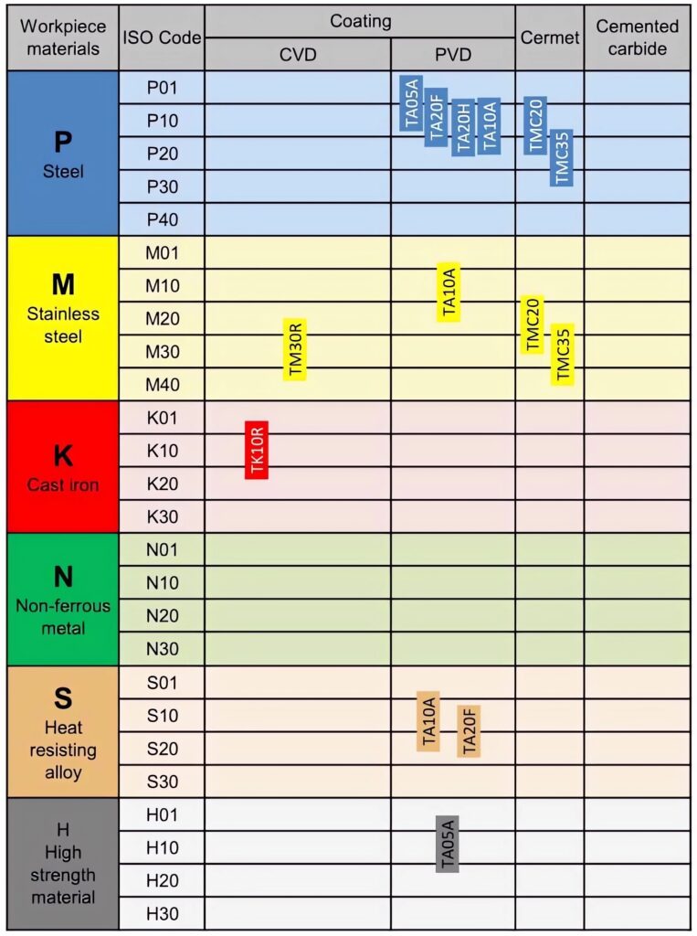
Recommended Grade for Turning Inserts
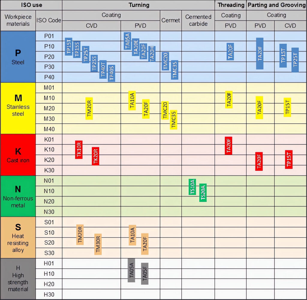
Recommended Grade for Milling Inserts
- Contact
Our team is ready to provide support
Truer Carbide is committed to providing efficient solutions to problems. Each team member has the expertise and experience to quickly understand and meet your needs.
