
- Carbide brazed tip
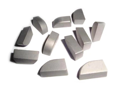
Carbide brazed tip
Carbide brazed tips are cutting tool inserts that consist of a small piece of carbide material securely bonded to a tool body or shank through a brazing process. The carbide material used in these tips is known for its exceptional hardness, wear resistance, and overall durability. The brazing process involves heating the carbide tip and the steel body to a high temperature and then fusing them together using a filler material.
One of the primary advantages of carbide brazed tips is their hardness. Carbide is significantly harder than high-speed steel (HSS), which makes these tips more resistant to wear and allows them to maintain sharp cutting edges for longer periods. The higher hardness also enables the tips to withstand higher cutting speeds and feeds, leading to increased productivity and improved machining efficiency.
Carbide brazed tips are incredibly versatile and find applications in a wide range of machining operations, including turning, milling, drilling, and boring. They can be used to machine various materials such as steels, cast iron, non-ferrous metals, and composites. The versatility of carbide brazed tips makes them suitable for both general-purpose and specialized applications.
Contact us if what you need is not shown here.
Introduction
Carbide brazed tips are cutting tool inserts made by brazing a small piece of carbide material onto a tool body or shank. Carbide is a hard and wear-resistant material known for its excellent cutting performance and durability. The brazing process involves fusing the carbide tip onto a steel body, forming a strong and rigid tool.
Carbide brazed tips are widely used in various machining operations, including turning, milling, drilling, and boring. They offer several advantages over traditional high-speed steel (HSS) tools: hardness and wear resistance, cutting speed and efficiency, versatility, surface finish.
Composition and Structure
Carbide brazed tips consist of tungsten carbide or cemented carbide materials bonded to a steel tool body. The carbide provides hardness and wear resistance, while the tool body offers support. A brazing process fuses the carbide and tool body using a filler material. The geometry and coatings of the carbide tip can be customized for specific machining applications.
Hardness
Carbide brazed tips exhibit exceptional hardness due to the tungsten carbide or cemented carbide material. Their hardness allows for effective cutting of various materials and provides resistance against wear, thus extending the tool’s lifespan.
Wear Resistance
Carbide brazed tips are highly wear-resistant, making them suitable for prolonged use in demanding machining applications. Their wear resistance ensures that the cutting edges stay sharp for longer, reducing the frequency of tool changes.
Toughness
The combination of carbide particles and a binder, typically cobalt, enhances the toughness of carbide brazed tips. This toughness enables them to withstand high cutting forces and prevents chipping or breakage during machining operations.
Toughness
Carbide brazed tips can withstand high temperatures generated during cutting. This heat resistance allows them to maintain their structural integrity and cutting performance even under challenging machining conditions.
High Speed Cutting
Carbide brazed tips are well-suited for high-speed cutting operations. Their hardness, wear resistance, and heat resistance enable them to withstand the higher cutting speeds, resulting in improved productivity and efficient machining.
Versatility
Carbide brazed tips can be used for a wide range of machining applications, including turning, milling, drilling, and boring. They are compatible with various materials, such as steels, cast iron, non-ferrous metals, and composites.
Surface Finish
Carbide brazed tips can produce high-quality surface finishes on machined parts. The sharp cutting edges and reduced tool deflection contribute to achieving superior surface finishes.
Cost-Effectiveness
Although carbide brazed tips may have a higher upfront cost compared to other cutting tools, their longer tool life and increased productivity deliver cost savings in the long run.
Carbide Material Preparation
The process starts with the preparation of the carbide material, typically tungsten carbide. Tungsten carbide powder is mixed with a binder material, often cobalt or another metal, to form a homogeneous mixture.
Pressing
The prepared carbide mixture is then compacted under high pressure using specialized equipment such as a press. This process, known as pressing or compacting, gives the carbide its desired shape and density.
Pre-Sintering
This involves heating the parts in a furnace at a specific temperature to remove any binders and to partially bond the carbide particles together. This pre-sintering step prepares the carbide for the final sintering process.
Sintering
They are placed in a high-temperature furnace and subjected to extreme heat. Sintering causes the carbide particles to bond together, resulting in a solid and dense carbide material.
Grinding and Shaping
The sintered carbide material is then carefully ground and shaped to achieve the desired geometry of the carbide tips. This process involves precision grinding machinery.
Tool Body Production
In parallel with the carbide manufacturing process, the tool bodies are produced using materials like high-quality steel. The tool bodies are shaped and machined to provide the necessary support and stability.
Brazing
The brazing filler material is applied between the carbide tip and the tool body. The assembled parts are then heated in a controlled environment, allowing the filler material to melt and create a metallurgical bond between the carbide and the tool body.
Finishing and Coating
This includes checking the dimensions, surface finishes, and ensuring the overall quality of the tips. Additionally, coatings such as TiN or TiCN may be applied to enhance the wear resistance and performance of the carbide tips.
Metal Cutting
Carbide brazed tips are widely used in metal cutting applications, particularly in machining operations. They are commonly applied in turning, milling, drilling, and threading processes to cut and shape various metals such as steel, stainless steel, cast iron, and aluminum. Carbide brazed tips offer high cutting speeds, excellent heat resistance, and prolonged tool life, making them ideal for demanding metal cutting tasks.
Woodworking
Carbide brazed tips are also utilized in woodworking applications. In woodworking operations such as shaping, profiling, and cutting, carbide brazed tips provide superior cutting performance and durability. They can handle the high speeds and tough conditions encountered in woodworking, providing clean and precise cuts on wood, plywood, particleboard, and other wood-based materials.
Mining and Construction
Carbide brazed tips are extensively used in mining and construction industries for cutting and drilling applications. They are commonly employed in rock drilling, tunneling, and excavation activities. Carbide tips exhibit excellent resistance to abrasion and impact, allowing them to withstand the harsh conditions encountered in mining and construction operations.
Wear Parts and Wear Protection
Carbide brazed tips are employed as wear parts and wear protection components in various industries. They are used in applications where resistance to abrasion, erosion, and wear is crucial. For example, carbide brazed tips are used in the manufacturing of wear plates, wear rings, wear bars, and cutting tools for agricultural machinery, earthmoving equipment, and industrial machinery.
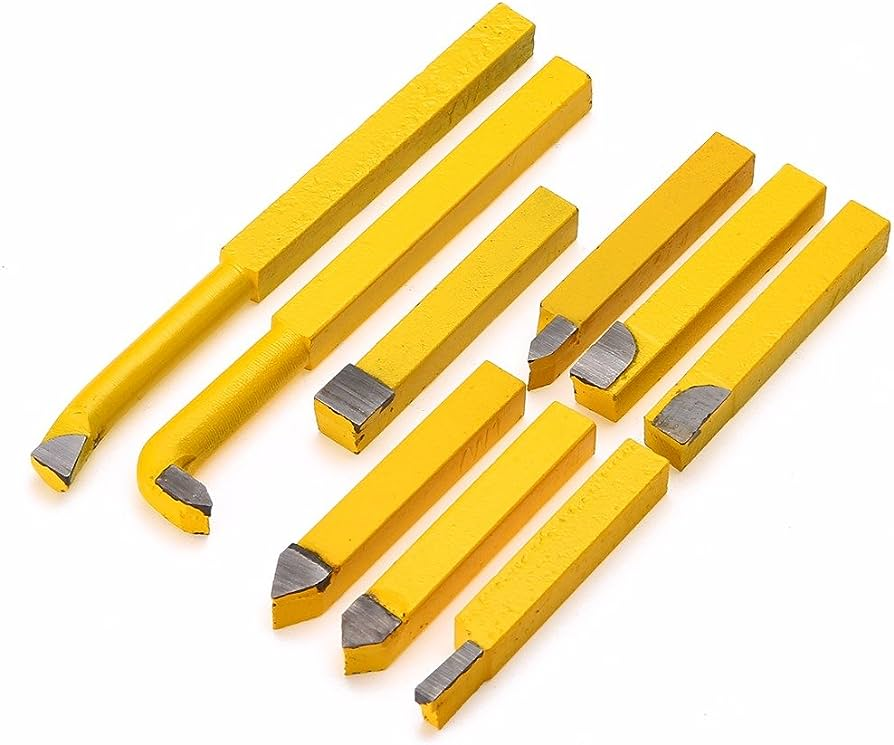
Carbide brazed tips are cutting tools that feature a tungsten carbide tip brazed onto a tool body, typically made of a softer metal. The brazing process involves using a filler metal to create a strong bond between the carbide tip and the tool body. This combination leverages the hardness and wear resistance of tungsten carbide with the toughness and flexibility of the tool body material, resulting in a highly effective cutting tool.
Coatings enhance wear resistance, reduce friction, improve chip flow, and increase tool life, especially in demanding applications involving high temperatures or abrasive materials.
Yes, they can be sharpened multiple times using specialized grinding wheels and techniques. However, it’s crucial to maintain the original blade geometry and avoid overheating during grinding.
Cemented carbide brazed tip inserts are cutting tools that feature a carbide tip brazed onto a tool body, providing exceptional hardness and wear resistance.
- Cutting Tools: For turning, milling, and boring.
- Woodworking Tools: Such as saw blades and routers.
- Mining and Drilling: Drill bits and cutter heads.
- Metalworking: For machining and shaping metals.
- Wear Parts: In industrial machinery for enhanced durability.
Yes, there are several carbide grades available for brazed tips, each with specific properties suited for different applications. Common carbide grades include C1, C2, C5, and C6.
Advantages include exceptional hardness, reduced friction and wear, improved heat resistance, longer tool life, and enhanced cutting performance. Disadvantages include higher cost, need for specialized equipment, potential brittleness under heavy impact, complex manufacturing process, and possible coating peel-off.
Carbide brazed tip geometry refers to the shape, angles, and dimensions of the cutting edge and surfaces of the tip. Key geometric parameters include:
- Rake Angle: The angle between the cutting edge and the workpiece surface. It influences chip formation and cutting force.
- Relief Angle: The angle between the flank of the tool and the workpiece surface, preventing rubbing and reducing friction.
- Cutting Edge Angle: The angle formed by the intersection of the rake and flank faces, affecting the tool’s strength and wear resistance.
- Corner Radius: The rounded edge at the tool’s tip, impacting surface finish and tool life.
The rake angle influences chip formation and cutting forces. A positive rake angle reduces cutting forces and improves efficiency but may compromise tool strength.
Round inserts with small nose radii provide a good balance of sharpness and strength for general-purpose finishing and contouring, while square inserts with sharp corners are ideal for finishing flat surfaces and creating precise 90-degree shoulders.
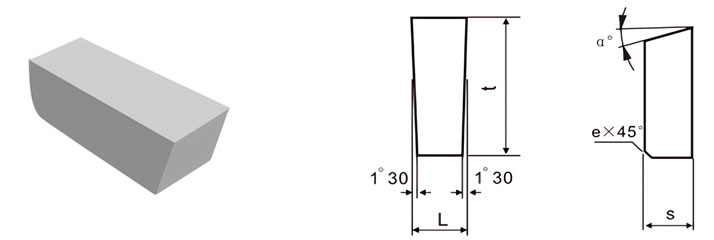
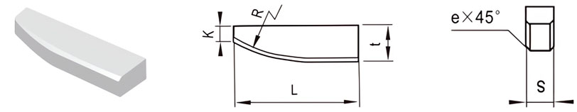
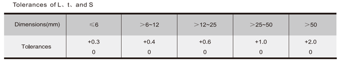
GB Brazed Tips Data
For Making Periphery Turning Tools, Boring Tools and Grooving Tools
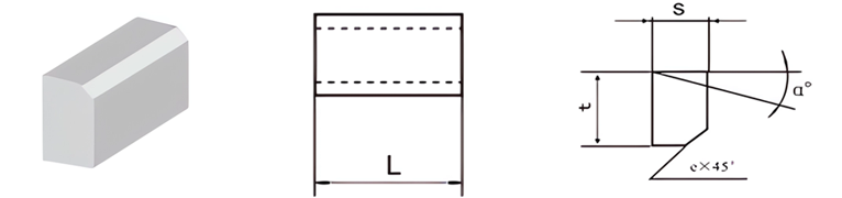
| Classification | L/mm | t/mm | S/mm | e/mm | α° |
|---|---|---|---|---|---|
| A1-0605-025 | 6 | 5 | 2.5 | / | 0 |
| A1-0807-030 | 8 | 7 | 3.0 | / | 0 |
| A1-1006-035 | 10 | 6 | 3.5 | 0.8 | 14 |
| A1-1210-040 | 12 | 10 | 4.0 | 0.8 | 14 |
| A1-1412-045 | 14 | 12 | 4.5 | 0.8 | 14 |
| A1-1412-040 | 14 | 12 | 4.0 | 0.8 | 14 |
| A1-1610-055 | 16 | 10 | 5.5 | 0.8 | 14 |
| A1-1610-045 | 16 | 10 | 4.5 | 0.8 | 14 |
| A1-1812-070 | 18 | 12 | 7.0 | 0.8 | 14 |
| A1-1812-065 | 18 | 12 | 6.5 | 0.8 | 14 |
| A1-1816-060 | 18 | 16 | 6.0 | 0.8 | 14 |
| A1-1812-060 | 18 | 12 | 6.0 | 0.8 | 14 |
| A1-2012-070 | 20 | 12 | 7.0 | 0.8 | 14 |
| A1-2215-085 | 22 | 15 | 8.5 | 0.8 | 14 |
| A1-2215-075 | 22 | 15 | 7.5 | 0.8 | 14 |
| A1-2218-070 | 22 | 18 | 7.0 | 0.8 | 14 |
| A1-2515-085 | 25 | 15 | 8.5 | 0.8 | 14 |
| A1-2520-100 | 25 | 20 | 10.0 | 0.8 | 14 |
| A1-3016-100 | 30 | 16 | 10.0 | 0.8 | 14 |
| A1-3620-100 | 36 | 20 | 10.0 | 0.8 | 14 |
| A1-4018-105 | 40 | 18 | 10.5 | 1.2 | 14 |
| A1-5020-105 | 50 | 20 | 10.5 | 1.2 | 14 |
| A1-6022-105 | 60 | 22 | 10.5 | 1.2 | 14 |
| A1-7025-120 | 70 | 25 | 12.0 | 1.2 | 14 |
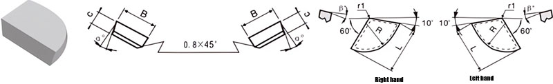
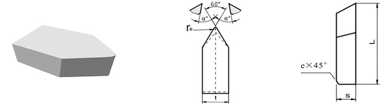
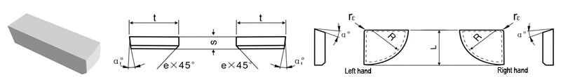
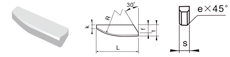
For Making Boring and End Turning Tools
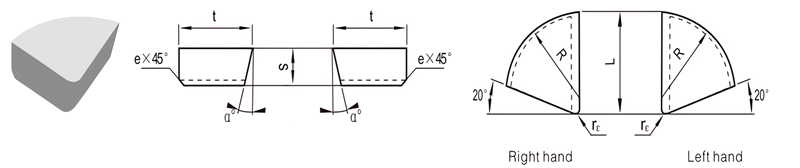
| Classification | L/mm | t/mm | S/mm | R/mm | rℇmm | e/mm | α° | |
|---|---|---|---|---|---|---|---|---|
| R.H. | L.H. | |||||||
| A2-0807-025 | / | 8 | 7 | 2.5 | 7 | 0.5 | / | 0 |
| A2-1008-030 | / | 10 | 8 | 3.0 | 8 | 1.0 | / | 0 |
| A2-1210-045 | / | 12 | 10 | 4.5 | 10 | 1.0 | 0.8 | 14 |
| A2-1614-060 | A2-1614-060LH | 16 | 14 | 6.0 | 14 | 1.0 | 0.8 | 14 |
| A2-2018-070 | A2-2018-070LH | 20 | 18 | 7.0 | 18 | 1.0 | 0.8 | 14 |
| A2-2520-080 | A2-2520-080LH | 25 | 20 | 8.0 | 20 | 1.0 | 0.8 | 14 |
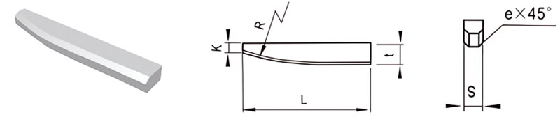
For Making Boring and End Turning Tools
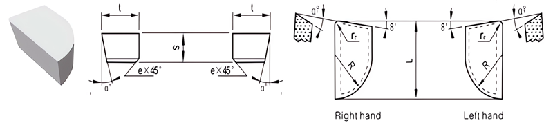
| Classification | L/mm | t/mm | S/mm | R/mm | rℇmm | e/mm | α° | α1° | |
|---|---|---|---|---|---|---|---|---|---|
| R.H. | L.H. | ||||||||
| A3-1006-030 | / | 10 | 6 | 3.0 | 6 | 1 | / | 0 | 0 |
| A3-1207-040 | A3-1207-040LH | 12 | 7 | 4.0 | 7 | 1 | 0.8 | 14 | 5 |
| A3-1509-060 | A3-1509-060LH | 15 | 9 | 6.0 | 9 | 1 | 0.8 | 14 | 5 |
| A3-1509-050 | A3-1509-050LH | 15 | 9 | 5.0 | 9 | 1 | 0.8 | 14 | 5 |
| A3-2011-070 | A3-2011-070LH | 20 | 11 | 7.0 | 11 | 1 | 0.8 | 14 | 5 |
| A3-2011-065 | A3-2011-065 | 20 | 11 | 6.5 | 11 | 1 | 0.8 | 14 | 5 |
| A3-2011-060 | A3-2011-060LH | 20 | 11 | 6.0 | 11 | 1 | 0.8 | 14 | 5 |
| A3-2514-080 | A3-2514-080LH | 25 | 14 | 8.0 | 14 | 1 | 0.8 | 14 | 5 |
| A3-2514-070 | A3-2514-070LH | 25 | 14 | 7.0 | 14 | 1 | 0.8 | 14 | 5 |
| A3-2514-060 | / | 25 | 14 | 6.0 | 14 | 1 | 0.8 | 14 | 5 |
| A3-3016-095 | A3-3016-095LH | 30 | 16 | 9.5 | 16 | 1 | 0.8 | 14 | 5 |
| A3-4018-105 | A3-4018-105LH | 40 | 18 | 10.5 | 18 | 1 | 1.2 | 14 | 5 |
For Making Boring Tools and Periphery & Face Turning Tools
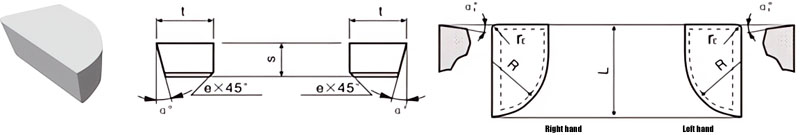
| Classification | L/mm | t/mm | S/mm | R/mm | rℇmm | e/mm | α° | α1° | |
|---|---|---|---|---|---|---|---|---|---|
| R.H. | L.H. | ||||||||
| A4-0605-025 | / | 6 | 5 | 2.5 | 5.0 | 0.5 | / | 0 | 0 |
| A4-0806-030 | / | 8 | 6 | 3.0 | 6.0 | 0.5 | / | 0 | 0 |
| A4-1006-035 | A4-1006-035LH | 10 | 6 | 3.5 | 6.0 | 1.0 | / | 14 | 8 |
| A4-1208-045 | A4-1208-045LH | 12 | 8 | 4.5 | 8.0 | 1.0 | 0.8 | 14 | 8 |
| A4-1610-055 | A4-1610-055LH | 16 | 10 | 5.5 | 10.0 | 1.0 | 0.8 | 14 | 8 |
| A4-2012-070 | A4-2012-070LH | 20 | 12 | 7.0 | 12.5 | 1.0 | 0.8 | 14 | 8 |
| A4-2515-085 | A4-2515-085LH | 25 | 15 | 8.5 | 16.0 | 1.0 | 0.8 | 14 | 8 |
| A4-3016-060 | A4-3016-060LH | 30 | 16 | 6.0 | 16.0 | 1.0 | 0.8 | 14 | 8 |
| A4-3016-095 | A4-3016-095LH | 30 | 16 | 9.5 | 16.0 | 1.0 | 0.8 | 14 | 8 |
| A4-4018-080 | A4-4018-080LH | 40 | 18 | 8.0 | 18.0 | 1.0 | 0.8 | 14 | 8 |
| A4-4018-105 | A4-4018-105LH | 40 | 18 | 10.5 | 18.0 | 1.0 | 1.2 | 14 | 8 |
| A4-5020-080 | A4-5020-080LH | 50 | 20 | 8.0 | 20.0 | 1.5 | 0.8 | 14 | 8 |
| A4-5020-120 | A4-5020-120LH | 50 | 20 | 12.0 | 20.0 | 1.5 | 1.2 | 14 | 8 |
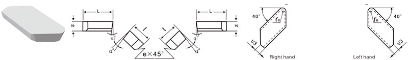
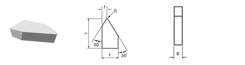
For Making Straight Periphery Turning Tolls, Through-Hole Boring Tools, End Milling Tools
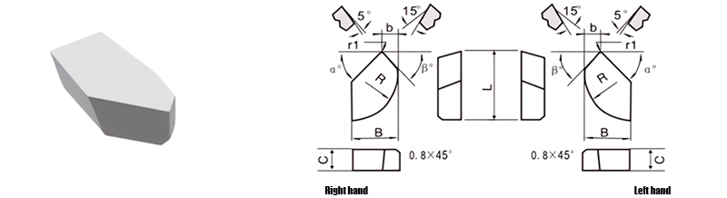
| Classification | L/mm | B/mm | C/mm | b/mm | R/mm | α° | β° | |
|---|---|---|---|---|---|---|---|---|
| R.H. | L.H. | |||||||
| A5-1510-045 | A5-1510-045LH | 15.0 | 10.0 | 4.5 | 5 | 10 | 45 | 40 |
| A5-1812-055 | A5-1812-055LH | 18.0 | 12.0 | 5.5 | 4 | 12 | 45 | 50 |
For Making Boring Tools & Periphery Turning Tools
| Classification | L/mm | B/mm | C/mm | R/mm | α° | β° | |
|---|---|---|---|---|---|---|---|
| R.H. | L.H. | ||||||
| A6-1208-030 | A6-1208-030LH | 12.0 | 8.0 | 3 | 8 | 14 | 5 |
| A6-1510-040 | A6-1510-040LH | 15.0 | 10.0 | 4 | 10 | 14 | 5 |
| A6-1812-045 | A6-1812-045LH | 18.0 | 12.0 | 4.5 | 12 | 14 | 5 |
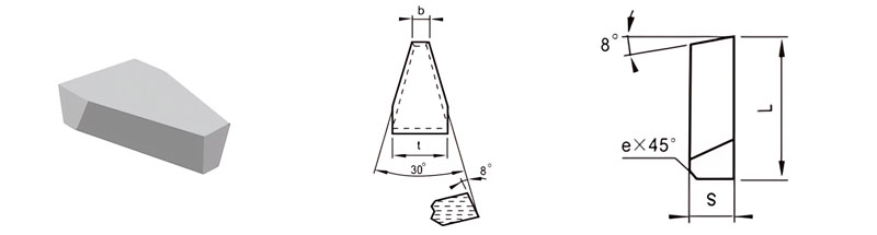
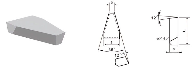
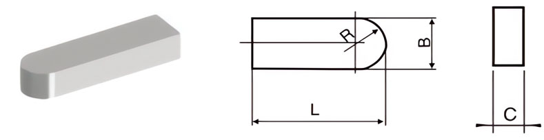
For Making Formed Turning Tools and Dovetail Cutters
| Classification | L/mm | t/mm | S/mm | rℇmm | e/mm | α° | α1° | |
|---|---|---|---|---|---|---|---|---|
| R.H. | L.H. | |||||||
| B1-0806-030 | / | 8 | 6 | 3 | 1.5 | / | 0 | 0 |
| B1-1208-040 | B1-1208-040LH | 12 | 8 | 4 | 1.5 | 1.0 | 10 | 5 |
| B1-1610-050 | B1-1610-050LH | 16 | 10 | 5 | 1.5 | 1.0 | 10 | 5 |
| B1-2014-050 | B1-2014-050LH | 20 | 14 | 5 | 1.5 | 1.0 | 10 | 5 |
| B1-2016-070 | B1-2016-070LH | 20 | 16 | 7 | 1.5 | 1.5 | 10 | 5 |
| B1-2514-050 | B1-2514-050LH | 25 | 14 | 5 | 1.5 | 1.5 | 10 | 5 |
| B1-2518-080 | B1-2518-080LH | 25 | 18 | 8 | 1.5 | 1.5 | 10 | 5 |
| B1-3020-080 | B1-3020-080LH | 30 | 20 | 8 | 1.5 | 1.5 | 10 | 5 |
For Making Turned Tools for Machining Concave Radii and Railway Wheels
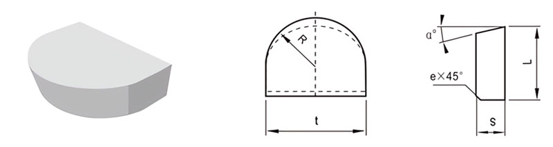
| Classification | L/mm | t/mm | S/mm | R/mm | e/mm | α° |
|---|---|---|---|---|---|---|
| B2-0808-030 | 8 | 8 | 3.0 | 4.0 | / | / |
| B2-1010-035 | 10 | 10 | 3.5 | 5.0 | 0.8 | 14 |
| B2-1212-045 | 12 | 12 | 4.5 | 6.0 | 0.8 | 14 |
| B2-1416-050 | 14 | 16 | 5.0 | 8.0 | 0.8 | 14 |
| B2-1620-060 | 16 | 20 | 6.0 | 10.0 | 0.8 | 14 |
| B2-2025-070 | 20 | 25 | 7.0 | 12.5 | 0.8 | 14 |
| B2-2530-080 | 25 | 30 | 8.0 | 15.0 | 0.8 | 14 |
| B2-2835-090 | 28 | 35 | 9.0 | 17.5 | 0.8 | 14 |
For Making Turned Tools for Radius Machining
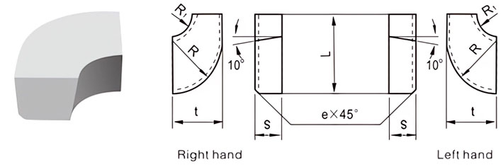
| Classification | L/mm | t/mm | S/mm | R/mm | R1/mm | e mm |
|
|---|---|---|---|---|---|---|---|
| R.H. | L.H. | ||||||
| B3-1208-040 | B3-1208-040LH | 12 | 8 | 4 | 8 | 3 | 0.8 |
| B3-1510-050 | B3-1510-050LH | 15 | 10 | 5 | 10 | 5 | 0.8 |
| B3-1812-060 | B3-1812-060LH | 18 | 12 | 6 | 12 | 6 | 0.8 |
| B3-2216-070 | B3-2216-070LH | 22 | 16 | 7 | 16 | 10 | 0.8 |
For Making Concave Radii and Railway Wheel Machining Tools
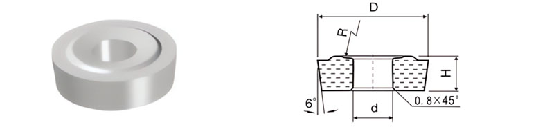
| Classification | D/mm | d/mm | H/mm | R/mm |
|---|---|---|---|---|
| B4-283100-100 | 28.3 | 10 | 10 | 35.0 |
| B4-330120-100 | 33.0 | 12 | 10 | 35.0 |
| B4-465150-120 | 46.5 | 15 | 12 | 41.7 |
For Making Turned Tools for Machining Thread and Periphery
| Classification | L/mm | t/mm | S/mm | rℇmm | e/mm | α° |
|---|---|---|---|---|---|---|
| C1-1004-030 | 10 | 4 | 3 | 0.5 | / | / |
| C1-1606-040 | 16 | 6 | 4 | 0.5 | 0.8 | 10 |
| C1-2008-050 | 20 | 8 | 5 | 0.5 | 0.8 | 10 |
| C1-2210-060 | 22 | 10 | 6 | 0.5 | 0.8 | 10 |
| C1-2512-070 | 25 | 12 | 7 | 0.8 | 0.8 | 10 |
For Making Turned Tools for Machining Thread and Periphery
| Classification | L/mm | t/mm | S/mm | rℇmm |
|---|---|---|---|---|
| C1-A-1065-028 | 10 | 6.5 | 2.8 | 0.5 |
| C1-A-1608-030 | 16 | 8.0 | 3.0 | 0.5 |
| C1-A-2010-040 | 20 | 10.0 | 4.0 | 0.5 |
For Making Finishingh Turned Tools for Machining Thread and Periphery
| Classification | L/mm | t/mm | S/mm | b/mm | e/mm |
|---|---|---|---|---|---|
| C2-1507-040 | 15 | 7 | 4 | 1.8 | 0.8 |
| C2-1810-050 | 18 | 10 | 5 | 3.1 | 0.8 |
| C2-2314-050 | 23 | 14 | 5 | 4.9 | 0.8 |
| C2-2818-060 | 28 | 18 | 6 | 7.7 | 0.8 |
| C2-3628-070 | 36 | 28 | 7 | 13.1 | 0.8 |
For Making Parting Tools and Grooving Tools
| Classification | L/mm | t/mm | S/mm | e/mm | α° |
|---|---|---|---|---|---|
| C3-03512-030 | 3.5 | 12 | 3 | / | / |
| C3-04514-040 | 4.5 | 14 | 4 | 0.8 | 14 |
| C3-05517-050 | 5.5 | 17 | 5 | 0.8 | 14 |
| C3-06517-060 | 6.5 | 17 | 6 | 0.8 | 14 |
| C3-06510-060 | 6.5 | 10 | 6 | 0.8 | 14 |
| C3-08520-070 | 8.5 | 20 | 7 | 0.8 | 14 |
| C3-08511-070 | 8.5 | 11 | 7 | 0.8 | 14 |
| C3-10522-080 | 10.5 | 22 | 8 | 0.8 | 14 |
| C3-10512-080 | 10.5 | 12 | 8 | 0.8 | 14 |
| C3-12522-100 | 12.5 | 22 | 10 | 0.8 | 14 |
| C3-12512-100 | 12.5 | 12 | 10 | 0.8 | 14 |
| C3-16525-110 | 16.5 | 25 | 11 | 1.2 | 14 |
For Making Grooving Tools of V-Belt Pulley
| Classification | L/mm | t/mm | S/mm | b/mm | e/mm |
|---|---|---|---|---|---|
| C4-2012-050 | 20 | 12 | 5 | 3.0 | 0.8 |
| C4-2516-050 | 25 | 16 | 5 | 4.0 | 0.8 |
| C4-3020-060 | 30 | 20 | 6 | 5.5 | 0.8 |
For Making Turning Tools of Rolls for Flour Production
| Classification | L/mm | B/mm | C/mm | R/mm |
|---|---|---|---|---|
| C5-3940-040 | 39 | 4.0 | 4.0 | 2 |
| C5-4560-040 | 45 | 6.0 | 4.0 | 3 |
For Making End Milling, Periphery Turning and Boring Tools
| Classification | L/mm | t/mm | S/mm | R/mm | rℇmm | e/mm | α° | α1° | |
|---|---|---|---|---|---|---|---|---|---|
| R.H. | L.H. | ||||||||
| D1-1012-030 | D1-1012-030LH | 10 | 12 | 3.0 | 10.0 | 0.5 | / | 0 | 0 |
| D1-1215-035 | D1-1215-035LH | 12 | 15 | 3.5 | 12.5 | 0.5 | 0.8 | 10 | 6 |
| D1-1620-040 | D1-1620-040LH | 16 | 20 | 4.0 | 16.0 | 1.0 | 0.8 | 10 | 6 |
For Making Keyway & End Milling Tools and Broaching Bits
| Classification | L/mm | t/mm | S/mm | K/mm | R/mm | e/mm |
|---|---|---|---|---|---|---|
| E3-12060-015 | 12 | 6.0 | 1.5 | 1.5 | 20 | / |
| E3-15035-020 | 15 | 3.5 | 2.0 | 1.5 | 20 | / |
| E3-15070-020 | 15 | 7.0 | 2.0 | 1.5 | 20 | / |
| E3-20045-025 | 20 | 4.5 | 2.5 | 2.5 | 25 | / |
| E3-20060-035 | 20 | 6.0 | 3.5 | 2.5 | 25 | 0.5 |
| E3-20090-025 | 20 | 9.0 | 2.5 | 2.5 | 25 | / |
| E3-25080-030 | 25 | 8.0 | 3.0 | 3.5 | 30 | 0.5 |
| E3-25150-030 | 25 | 15.0 | 3.0 | 3.5 | 30 | 0.5 |
| E3-30100-040 | 30 | 10.0 | 4.0 | 3.5 | 30 | 0.5 |
| E3-30090-040 | 30 | 9.0 | 4.0 | 3.5 | 30 | 0.5 |
| E3-30210-040 | 30 | 21.0 | 4.0 | 3.5 | 30 | 0.5 |
| E3-35100-050 | 35 | 10.0 | 5.0 | 3.5 | 30 | 0.8 |
| E3-40120-050 | 40 | 12.0 | 5.0 | 3.5 | 30 | 0.8 |
| E3-45120-060 | 45 | 12.0 | 6.0 | 3.5 | 30 | 0.8 |
For Making Broaching Drill Bits
| Classification | L/mm | t/mm | S/mm | f/mm | K/mm | R/mm | e/mm |
|---|---|---|---|---|---|---|---|
| E4-15040-020 | 15 | 4.0 | 2.0 | 2.5 | 1.5 | 15 | / |
| E4-18050-025 | 18 | 5.0 | 2.5 | 3.5 | 1.5 | 20 | / |
| E4-20060-030 | 20 | 6.0 | 3.0 | 5 | 1.5 | 25 | 0.5 |
| E4-25080-035 | 25 | 8.0 | 3.5 | 6 | 2 | 25 | 0.5 |
| E4-30100-040 | 30 | 10.0 | 4.0 | 8 | 2 | 30 | 0.5 |
For Making Reamers
| Classification | L/mm | t/mm | S/mm | K/mm | R/mm | e/mm |
|---|---|---|---|---|---|---|
| E5-15025-013 | 15 | 2.5 | 1.3 | 1.5 | 20 | / |
| E5-18030-015 | 18 | 3.0 | 1.5 | 1.5 | 25 | / |
| E5-22035-020 | 22 | 3.5 | 2.0 | 1.5 | 25 | / |
| E5-25040-025 | 25 | 4.0 | 2.5 | 2 | 30 | / |
| E5-30050-030 | 30 | 5.0 | 3.0 | 2 | 30 | 0.5 |
| E5-40060-035 | 40 | 6.0 | 3.5 | 2 | 30 | 0.5 |
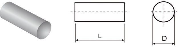
For Making Core Clampers for Lathes and Periphery Grinders
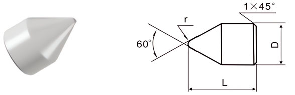
| Classification | D/mm | L/mm | r/mm |
|---|---|---|---|
| F1-0815 | 8 | 15 | 1.0 |
| F1-1014 | 10 | 14 | 1.0 |
| F1-1220 | 12 | 20 | 1.5 |
| F1-1524 | 15 | 24 | 1.5 |
| F1-1828 | 18 | 28 | 2.0 |
| F1-2435 | 24 | 35 | 2.0 |
| F1-3040 | 30 | 40 | 2.5 |
| F1-3650 | 36 | 50 | 2.5 |
| F1-4060 | 40 | 60 | 3.0 |
For Making Guides of Broaching Drill Bits
| Classification | L/mm | B/mm | C/mm | R/mm |
|---|---|---|---|---|
| F2-16080-050 | 16 | 8.0 | 5.0 | 4 |
| F2-16100-050 | 16 | 10.0 | 5.0 | 5 |
| F2-16120-060 | 16 | 12.0 | 6.0 | 6 |
| F2-18025-025 | 18 | 2.5 | 2.5 | 1.25 |
| F2-20030-030 | 20 | 3.0 | 3.0 | 1.5 |
| F2-25050-040 | 25 | 5.0 | 4.0 | 2.5 |
| F2-30060-050 | 30 | 6.0 | 5.0 | 3 |
| F2-30080-050 | 30 | 8.0 | 5.0 | 4 |
| F2-30100-050 | 30 | 10.0 | 5.0 | 5 |
| F2-30120-060 | 30 | 12.0 | 6.0 | 6 |
| F2-35080-050 | 35 | 8.0 | 5.0 | 4 |
| F2-30080-050 | 30 | 8.0 | 5.0 | 4 |
| F2-45120-060 | 45 | 12.0 | 6.0 | 6 |
For Making Detachable Boring Tools and Wear Parts
| Classification | D/mm | L/mm |
|---|---|---|
| F3-3510 | 3.5 | 10 |
| F3-4512 | 4.5 | 12 |
| F3-5515 | 5.5 | 15 |
| F3-6518 | 6.5 | 18 |
| F3-7520 | 7.5 | 20 |
| F3-8522 | 8.5 | 22 |
For Making Broaching Drill Bits
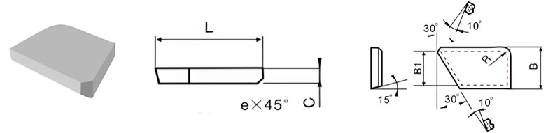
| Classification | L/mm | B/mm | B1/mm | C/mm | R/mm |
|---|---|---|---|---|---|
| S-A-16070-020 | 16 | 7.0 | 6.3 | 2 | 3 |
| S-A-20106-030 | 20 | 10.6 | 9.5 | 3 | 4 |
| S-A-25145-045 | 25 | 14.5 | 12.9 | 4.5 | 4 |
| S-A-30180-045 | 30 | 18.0 | 16.0 | 4.5 | 4 |
For Making Broaching Drill Bits
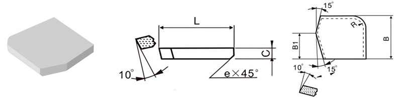
| Classification | L/mm | B/mm | B1/mm | C/mm | R/mm | e/mm |
|---|---|---|---|---|---|---|
| S-B-2522-045 | 25 | 22 | 14 | 4.5 | 8 | 0.8 |
| S-B-3028-050 | 30 | 28 | 17 | 5.0 | 8 | 0.8 |
| S-B-3533-060 | 35 | 33 | 20 | 6.0 | 10 | 1.2 |
| S-B-4040-060 | 40 | 40 | 23 | 6.0 | 10 | 1.2 |
ISO Brazed Tips Data
| Classification | L/mm | t/mm | S/mm | r/mm | α° |
|---|---|---|---|---|---|
| A5 | 5 | 3 | 2 | 2 | / |
| A6 | 6 | 4 | 3 | 3 | / |
| A8 | 8 | 5 | 3 | 3 | / |
| A10 | 10 | 6 | 4 | 4 | 18 |
| A12 | 12 | 8 | 5 | 5 | 18 |
| A16 | 16 | 10 | 6 | 6 | 18 |
| A20 | 20 | 12 | 7 | 7 | 18 |
| A25 | 25 | 14 | 8 | 8 | 18 |
| A32 | 32 | 18 | 10 | 10 | 18 |
| A40 | 40 | 22 | 12 | 12 | 18 |
| A50 | 50 | 25 | 14 | 14 | 18 |
| Classification | L/mm | t/mm | S/mm | r/mm | α° |
|---|---|---|---|---|---|
| B5 | 5 | 3 | 2 | 2.0 | / |
| B6 | 6 | 4 | 3 | 2.5 | / |
| B8 | 8 | 5 | 3 | 3.0 | / |
| B10 | 10 | 6 | 4 | 4.0 | 18 |
| B12 | 12 | 8 | 5 | 5.0 | 18 |
| B16 | 16 | 10 | 6 | 6.0 | 18 |
| B20 | 20 | 12 | 7 | 7.0 | 18 |
| B25 | 25 | 14 | 8 | 8.0 | 18 |
| B32 | 32 | 18 | 10 | 10.0 | 18 |
| B40 | 40 | 22 | 12 | 12.0 | 18 |
| B50 | 50 | 25 | 14 | 14.0 | 18 |
| Classification | L/mm | t/mm | S/mm | α° |
|---|---|---|---|---|
| C5 | 5 | 3 | 2.0 | / |
| C6 | 6 | 4 | 2.5 | / |
| C8 | 8 | 5 | 3.0 | / |
| C10 | 10 | 6 | 4.0 | 18 |
| C12 | 12 | 8 | 5.0 | 18 |
| C16 | 16 | 10 | 6.0 | 18 |
| C20 | 20 | 12 | 7.0 | 18 |
| C25 | 25 | 14 | 8.0 | 18 |
| C32 | 32 | 18 | 10.0 | 18 |
| C40 | 40 | 22 | 12.0 | 18 |
| C50 | 50 | 25 | 14.0 | 18 |
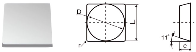
Carbide Inserts for Milling Blades Data
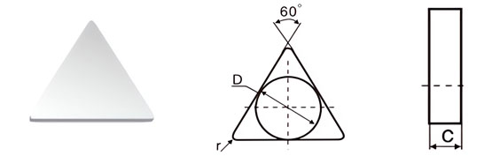
| Classification | D±Tol./mm | C±0.13/mm | r/mm |
|---|---|---|---|
| T-0-07-05 | 7.34±0.08 | 3.30 | 0.5 |
| T-0-10-05 | 10.34±0.08 | 3.85 | 0.5 |
| T-0-13-05 | 13.45±0.13 | 4.85 | 0.5 |
| T-0-13-10 | 13.45±0.13 | 4.85 | 1.0 |
| T-0-16-10 | 16.50±0.18 | 5.85 | 1.0 |
| T-0-16-15 | 16.50±0.18 | 5.85 | 1.5 |
| T-0-16-20 | 16.50±0.18 | 5.85 | 2.0 |

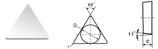
| Classification | D±Tol./mm | C±0.13/mm | r/mm |
|---|---|---|---|
| T-8-07-05 | 7.34±0.08 | 3.30 | 0.5 |
| T-8-10-05 | 10.34±0.08 | 3.85 | 0.5 |
| T-8-13-05 | 13.45±0.13 | 4.85 | 0.5 |
| T-8-13-10 | 13.45±0.13 | 4.85 | 1.0 |
| T-8-16-05 | 16.50±0.18 | 5.85 | 0.5 |
| T-8-16-10 | 16.50±0.18 | 5.85 | 1.0 |
| T-8-16-20 | 16.50±0.18 | 5.85 | 2.0 |
| Classification | D±Tol./mm | C±0.13/mm | r/mm |
|---|---|---|---|
| T-11-07-05 | 7.34±0.1 | 3.30 | 0.5 |
| T-11-10-05 | 10.34±0.1 | 3.85 | 0.5 |
| T-11-13-05 | 13.45±0.15 | 4.85 | 0.5 |
| T-11-13-10 | 13.45±0.15 | 4.85 | 1.0 |
| T-11-13-05 | 13.45±0.15 | 5.10 | 0.5 |
| T-11-16-05 | 16.50±0.18 | 5.85 | 0.5 |
| T-11-16-10 | 16.50±0.18 | 5.85 | 1.0 |
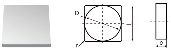
| Classification | D±Tol./mm | C±0.13/mm | r/mm |
|---|---|---|---|
| S-0-10-05 | 10.4±0.08 | 3.85 | 0.5 |
| S-0-13-05 | 13.4±0.13 | 4.85 | 0.5 |
| S-0-13-10 | 13.4±0.13 | 4.85 | 1.0 |
| S-0-16-05 | 16.5±0.18 | 4.85 | 0.5 |
| S-0-16-10 | 16.5±0.18 | 4.85 | 1.0 |
| S-0-19-10 | 19.6±0.18 | 5.85 | 1.0 |
| S-0-19-20 | 19.6±0.18 | 5.85 | 2.0 |
| S-0-25-10 | 25.6±0.25 | 7.35 | 1.0 |
| S-0-25-20 | 25.6±0.25 | 7.35 | 2.0 |
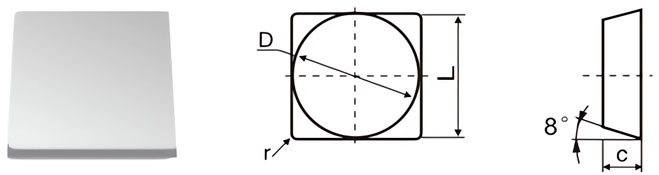
| Classification | D±Tol./mm | C±0.13/mm | r/mm |
|---|---|---|---|
| S-8-10-05 | 10.4±0.08 | 3.30 | 0.5 |
| S-8-13-05 | 13.4±0.13 | 3.85 | 0.5 |
| S-8-13-05 | 13.4±0.13 | 4.85 | 0.5 |
| S-8-13-10 | 13.4±0.13 | 4.85 | 1.0 |
| S-8-16-05 | 16.5±0.18 | 4.85 | 0.5 |
| S-8-16-10 | 16.5±0.18 | 4.85 | 1.0 |
| S-8-16-15 | 16.5±0.18 | 4.85 | 1.5 |
| S-8-19-10 | 19.6±0.18 | 5.85 | 1.0 |
| S-8-19-20 | 19.6±0.18 | 5.85 | 2.0 |
| S-8-25-10 | 25.6±0.25 | 7.35 | 1.0 |
| S-8-25-20 | 25.6±0.25 | 7.35 | 2.0 |
| Classification | D±Tol./mm | C±0.13/mm | r/mm |
|---|---|---|---|
| S-11-10-05 | 10.4±0.10 | 3.30 | 0.5 |
| S-11-13-05 | 13.4±0.15 | 3.50 | 0.5 |
| S-11-13-05 | 13.4±0.15 | 3.85 | 0.5 |
| S-11-13-10 | 13.4±0.15 | 4.85 | 0.5 |
| S-11-13-10 | 13.4±0.15 | 4.85 | 1.0 |
| S-11-13-05 | 13.4±0.15 | 5.10 | 0.5 |
| S-11-16-05 | 16.5±0.18 | 4.85 | 0.5 |
| S-11-16-10 | 16.5±0.18 | 5.10 | 0.5 |
| S-11-16-15 | 16.5±0.18 | 4.85 | 1.0 |
| S-11-16-15 | 16.5±0.18 | 4.85 | 1.5 |
| S-11-19-10 | 19.5±0.18 | 5.85 | 1.0 |
| S-11-19-20 | 19.5±0.18 | 5.85 | 2.0 |
| S-11-25-10 | 25.6±0.25 | 7.35 | 1.0 |
| S-11-25-20 | 25.6±0.25 | 7.35 | 2.0 |
Grades for Carbide Brazed Cutting Tips
| Grade | Density/{g/cm³} | Hardness/{HRA} | TRS/{N/mm²} | ISO Code | Application Recommendation |
|---|---|---|---|---|---|
| K10UF | 14.70-14.95 | ≥93.0 | ≥3000 | K05 | Suitable for the finishing of cast iron and nonferrous metal. |
| YG3X | 15.00-15.20 | ≥92.5 | ≥1300 | ||
| YG3 | 15.15-15.30 | ≥91.5 | ≥1400 | ||
| YG6X | 14.70-14.85 | ≥91.7 | ≥1860 | K10 | Suitable for the finishing & semi-finishing of cast iron and nonferrous metals, and also for the machining of manganese steel and hardening steel. |
| YG6A | 14.85-15.05 | ≥92.0 | ≥1600 | ||
| YG6 | 14.85-15.05 | ≥90.5 | ≥1860 | K20 | Suitable for the roughing of cast iron and light alloys, ans also for milling of cast iron and low-alloy steel. |
| YG8 | 14.60-14.85 | ≥89.7 | ≥2060 | K30 | |
| YS8 | 13.70-14.10 | ≥92.5 | ≥1720 | M05 | For the finishing of iron-based & nickel-based high-temperature alloys, high-strength steels, chilled cast iron, heat resistant stainless steel, high manganese steel and hardened steel. |
| YW1 | 13.00-13.30 | ≥92.0 | ≥1600 | M10 | For the finishing and semi-finishing of stainless steel and common alloy steels. |
| YS2T | 14.25-14.55 | ≥91.0 | ≥2160 | ||
| YT03 | 14.75-14.95 | ≥91.5 | ≥1860 | ||
| YW2 | 12.90-13.30 | ≥91.0 | ≥1680 | M20 | For the semi-finishing of stainless steel and low-alloy steel, mainly for the machining of railway wheel hubs. |
| YW5 | 12.90-13.30 | ≥90.5 | ≥1680 | ||
| YT15 | 11.10-11.50 | ≥91.5 | ≥1600 | P10 | For the finishing & semi-finishing of steel and cast steel with a moderate feed rate and a rather high cutting speed. |
| YT14 | 11.20-11.60 | ≥91.0 | ≥1680 | P20 | For the finishing & semi-finishing of steel and cast steel with a moderate feed rate, and YS25 specially used for the milling of steel and cast steel. |
| YS25 | 12.80-13.20 | ≥90.5 | ≥2060 | ||
| YT5 | 12.60-13.00 | ≥90.0 | ≥1750 | P30 | For the heavy duty rough turning of steel and cast steel under unfavorable working conditions with a high feed rate, and YC30S specially for the milling of steel and cast steel. |
| YC30S | 12.80-13.00 | ≥89.5 | ≥1600 | ||
| YC40 | 12.80-13.30 | ≥89.5 | ≥1700 | P40 | For the heavy duty rough turning of steel and cast steel with a high feed rate, and also for face milling. |
- Contact
Our team is ready to provide support
Truer Carbide is committed to providing efficient solutions to problems. Each team member has the expertise and experience to quickly understand and meet your needs.