Carbide button inserts refer to round indexable inserts with hemispherical contact profiles made of cemented carbides or cermets for interrupted machining applications. Featuring multi-functional cutting edges, button inserts possess optimized geometries for grooving, parting and recessing operations demanding superior wear resistance, strength and shock damping.
Overview of carbide button inserts
Carbide button inserts offer:
- Extreme hardness supporting abrasion resistance
- Toughness and strength for resistance to chipping
- Thermal shock stability preventing crack propagation
- Positive geometries minimizing cutting forces
- Multi-directional tool forces accommodation
- Custom edge preparations and chip breakers
- Ease of indexability through rotational clamping
- Flatter contact promoting surface finish
These well-rounded cutting tool advantages drive uptake spanning automotive, aerospace, die-mold, medical, and general machining sectors. Button inserts support reliable, cost-effective interrupted and ramping cuts minimizing untimely tool failures or damage even under demanding regimes.
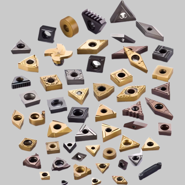
Types of Carbide Button Inserts
Major button insert varieties include:
| Type | Composition | Description |
|---|---|---|
| Cemented carbide | 94% tungsten carbide (WC) with 6% cobalt binder | Broadest application range |
| Cermet | 75% titanium carbonitride (Ti(C,N)) ceramic with 25% nickel/molybdenum binder | Superior high speed capability |
| Cubic boron nitride (CBN) | 60-90% CBN with ceramic/carbide binder | Exceptional wear resistance across hardness ranges |
| Polycrystalline diamond (PCD) | 80-95% synthetic diamond with cobalt binder | Ultimate low wear option for non-ferrous alloys |
These material choices span cost vs cutting performance considerations, allowing optimal selection.
Composition of carbide button inserts
Typical composition of common carbide button insert types:
| Material | Major Constituents | Role |
|---|---|---|
| Cemented carbide | 88-94% tungsten carbide (WC)<br>6-12% cobalt binder | Hard constituent providing wear resistance<br>Ductile binder imparting fracture strength |
| Cermet | 65-80% titanium carbonitride (Ti(C<sub>0.5</sub>N<sub>0.5</sub>)) <br> 20-35% nickel/molybdenum binder | Hard ceramic carbide phase <br> Toughening metallic binder |
| PCBN | 80-90% CBN, 10-20% ceramic binder | Abrasive CBN material along with carbide/ceramic binder |
| PCD | 80-90% diamond, 10-20% cobalt binder | Hard diamond grains providing cutting capability <br> Metallic cobalt binder affording thermal resistance |
These compositions promote tailored hardness, strength and shock resistance.
Properties of carbide button inserts
Well-designed button inserts offer a useful balance across attributes:
Physical Properties
| Property | Carbide | Cermet | PCBN | PCD |
|---|---|---|---|---|
| Density | 12-15 g/cm<sup>3</sup> | 5.3-5.7 g/cm<sup>3</sup> | 3.45-3.55 g/cm<sup>3</sup> | 3.15-3.50 g/cm<sup>3</sup> |
| Hardness | 1600-2200 HV | 1600-2100 HV | 4000-5000 HV | 8000 HV |
| Transverse Rupture Strength | 350-600 MPa | 100-350 MPa | 600-1200 MPa | 500-1350 MPa |
| Fracture Toughness | 9-12 MPa√m | 7-15 MPa√m | 6-9 MPa√m | ∼15 MPa√m |
Cemented carbides offer balanced hardness and fracture resistance while advanced cermet, CBN and PCD boast extreme hardness levels.
Cutting Performance
Relative tool material behavior during machining:
| Parameter | Carbide | Cermet | PCBN | PCD |
|---|---|---|---|---|
| Abrasion Wear Resistance | Good | Better | Best | Excellent |
| Chemical/Diffusive Wear Resistance | Good | Better | Excellent | Excellent |
| Thermal Shock Resistance | Good | Superior | Fair | Poor |
| Toughness and Impact Strength | Good | Fair | Poor | Poor |
| High Speed Machining Capability | Good | Excellent | Very Good | Fair |
Cermets and PCBN boast temperature and wear performance critical for high productivity button turning and grooving. PCD suits lower cutting speeds better.
Design and Geometry of carbide button inserts
Salient button insert features contributing to reliable function:
| Parameter | Details | Advantages |
|---|---|---|
| Contact profile | Precision hemispherical contact curve | Point contact generates low cutting forces; flatness control supports finish requirements |
| Nose radius | Sharp for parting, larger for turning/grooving | Balance of strength and contained cutting forces through edge radius; positive cutting action |
| Clearance angles | Typically 7° side relief below contact | Deflects chips and lubricant access while resisting edge breakdown |
| Wiper flats | Small facets interrupting curvature | Facilitate surface finish control and stabilize insert against vibration |
Positive geometry coupled with clamping flexibility minimizes damaging loads and deflection.
Tool Holders of carbide button inserts
Special fixtures accurately present inserts onto the workpiece:
| Holder | Description | Mounting Method |
|---|---|---|
| Solid style | Simple bars with machined pockets contacting half of insert | Fixture clamping into tool block; limited positioning flexibility |
| Cartridge style | Indexable carbide cartridges with precision insert seats | Screw clamping provides better rigidity and depth control |
| Tool block system | Mini tool block holding multiple inserts, cartridges or fixed tools | Lathe turret or block tool holder interface; high accuracy |
Dedicated holders limit runout below 0.01 mm helping execute precision grooves, slots and part profiles.
carbide button inserts Manufacturing
Button insert production steps:
1. Milling powders – Carbides, ceramics and binder constituents undergo wet ball milling
2. Spray drying – Granulation builds flowability and consistency
3. Compaction – Uniaxial followed by isostatic pressing generates green density
4. Presintering – Initial 1400°C cycle imparts strength for grinding
5. Edge grinding – Diamond dressing creates finished geometries and edge condition
6. Final sintering – Controlled heat treatment densifies microstructure
7. Brazing – Carbide plates are induction brazed onto steel shanks for assembled inserts
8. Coating – Special PVD, CVD coatings are applied to contact surfaces
9. Packaging – Protective packaging prevents edge or surface damage
Such extensive processing culminates in indexable inserts boasting complex cutting edge contours impossible through other means.
carbide button inserts Applications
Typical applications benefitting from carbide button insert capability:
Automotive
Grooving valve guide bores; cylinder head, block, crank and cam machining; engine component external turning
Aerospace
Rotor slotting, blade root profiling; frame and bulkhead recessing; missile motor case tapering
Medical and dental
Machining implants from tough stainless steels and Ti/CoCr alloys; orthodontic bracket shaping
Die and mold
Steel mold cavity plunging; graphite electrode profiling; H13 tool steel grooving
General machining
Parting-off stock; recessing and shouldering across materials; wide component grooving
Grades of carbide button inserts
Carbide buttons carry standardized ISO material designations:
| Grade | Composition | Characteristics |
|---|---|---|
| Cemented carbide | ||
| P20-P50 | WC-Co medium coarse | General machining steels/stainless |
| M10-M40 | WC-Co micrograin | High hardness, wear resistance |
| K20 | Mixed ceramics in WC-Co | High edge strength and temperature resistance |
| Cermet | ||
| T15-T50 | TiCN-NiMo | High speed steels and hardened metals |
| MT10-MT50 | TiCN-NiMo micrograin | Superior wear resistance |
Additionally, unique suffixes get appended indicating special characteristics like edge treatments.
Dimensions of carbide button inserts
Typical metric range spans:
| Parameter | Range |
|---|---|
| Inscribed Circle | 3 mm to 25 mm |
| Insert Heights | 2 mm to 6 mm |
| Edge Radii | Sharp; 0.4 mm; 0.8 mm; 1.2 mm |
| Thicknesses | 1.5 mm to 4 mm |
Larger American ANSI and fractional sizes also available. Custom geometries possible based on application needs.
carbide button inserts Standards
Important specifications include:
- ISO 1832:2012 – Inserts for cutting tools
- ANSI B212.4 – Carbide Inserts, Hardened Steel
- JIS B4104 – Carbide Inserts for Machine Tools
carbide button inserts Suppliers
Leading global button insert manufacturers:
| Company | HQ |
|---|---|
| Iscar | Israel |
| Sandvik | Sweden |
| Sumitomo | Japan |
| Kyocera | Japan |
| Kennametal | USA |
| Walter Tools | Germany |
| Korloy | South Korea |
| Mapal | Germany |
These technology leaders shape evolving tool material and edge preparations advancing button insert utility across industry applications.
Cost Analysis
Representative costs for common varieties:
| Insert Type | Indicative Pricing |
|---|---|
| Carbide Button, Grade P20 | $12-18 per piece |
| Micrograin Carbide Button, Grade M20 | $15-22 per piece |
| TiCN Cermet Button, Grade T30 | $35-60 per piece |
| PCD Button, 2 mm height | $45-75 per piece |
| PCBN Button, 3 mm height | $65-95 per piece |
Larger sizes, special geometries and premium grades fetch higher prices. Savings result from insert indexability spreading costs over multiple cutting edges.
Pros and Cons
Advantages
- Extreme hardness supports wear resistance in roughing
- Can withstand high cutting speeds and feeds
- Positive geometry minimizes cutting forces
- Round shape diffuses concentrated stresses
- Facilitates light and interrupted cuts
- Allows multi-directional machining
- Enables precision slotting/grooving
- Simplifies indexable tooling logistics
- Coatings boost productivity and edge strength
Limitations
- Not suitable for continuous turning of longer lengths
- Lower edge strength than triangular inserts
- Prone to vibration under certain regimes
- Requires rigid setups preserving alignment
- Orientation needs indexing fixtures or tool blocks
- More expensive than replaceable tips per edge
- Finishing passes may show shoulder marks of diameter transitions
Recognizing applicability strengths and manageable limitations ensures optimal tool selection matching capability to needs.
FAQs
| Question | Answer |
|---|---|
| What are carbide button inserts? | Round indexable inserts with shaped contact profiles made of cemented carbides/cermets for light/interrupted cutting |
| What materials are button inserts made of? | Mainly cemented carbides of WC-Co composition; also advanced cermets, PCBN, PCD options |
| What operations use button style inserts? | Grooving, parting-off, recessing, plunging, slotting, profiling etc in turns, mills, drills |
| What are the benefits of carbide buttons? | Extreme wear resistance; positive geometry gives lower forces; multi-directed cutting; precision profiles |
| What dimensions are available? | Metric buttons of 3 mm to 25 mm sizes; also inch sizes. Heights of 2 to 6 mm typical |
| How are inserts designated? | Common ISO grades like P20, M25 etc denote composition. Suffixes indicate special features like chamfers or coatings |
| What causes inserts to fail prematurely? | Inadequate rigidity, built-up edge, poor coolant access, excessive feeds/speeds, edge chipping due to interrupted cuts |
| How can button life be maximized? | Choose size suiting rigidity demands; optimize feed/speed combo; ensure positive lead angles clearing chips effectively |
Summary
Button-style carbide inserts represent vital productivity tools turning challenging grooving, recessing and slotting operations into reliable, simplified tasks across application sectors. Carefully engineered geometries balancing strength against cutting forces unlock lighter regimes previously unfeasible while avoiding edge breakdown, enabling micron-level accuracy even on high-hardness materials.
As manufacturers demand solutions tackling shorter production runs, custom components and minimizing inventory, indexable button inserts facilitate just-in-time capability across niche to high-volume domains cost-effectively while pushing performance boundaries. With ongoing advances in indexable tooling platforms and ultra-wear resistant material science, hemispherical carbide technology stays poised to tackle ever-expanding aperture needs precisely.

