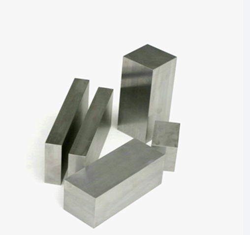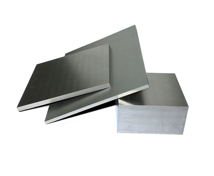
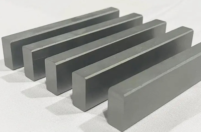
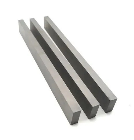
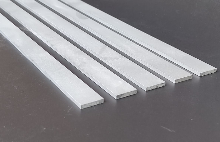
Pourquoi la planéité est importante Plaques de carbure
Avez-vous déjà essayé de placer une pièce de puzzle au mauvais endroit ? Elle pourrait presque s'emboîter, mais elle est juste assez décalée pour gâcher l'ensemble de l'image. C'est un peu ce qui se passe lorsque les plaques de carbure ne sont pas plates. Dans le domaine de la fabrication et de l'ingénierie de précision, le moindre écart de planéité peut perturber l'ensemble d'un processus : mauvaise étanchéité des matrices, usure irrégulière des machines et retouches coûteuses.
Le carbure, ultra-dur et résistant à l'usure, est un matériau de choix pour les applications d'outillage telles que les poinçons, les matrices, les plaques d'usure, etc. Toutefois, si la planéité n'est pas conforme à des tolérances strictes, la pièce risque d'être totalement inutilisable malgré la qualité du matériau. C'est pourquoi la planéité de précision n'est pas seulement un avantage, elle est non négociable.
La planéité a un impact sur tout, de la distribution de la chaleur à l'intégrité dimensionnelle et à l'ajustement mécanique. Dans les environnements soumis à de fortes contraintes, comme l'emboutissage ou le découpage des métaux, une mauvaise planéité entraîne des concentrations de contraintes, ce qui provoque des fissures ou une défaillance totale de la pièce. C'est comme essayer de couper un steak avec un couteau à beurre - c'est faisable, mais douloureusement inefficace.
Méthodes courantes pour tester la planéité
Pour tester la planéité, il ne suffit pas d'appliquer une règle sur une plaque. Les ingénieurs ont mis au point toute une série de méthodes pour obtenir une mesure au micron près. Voici comment les professionnels procèdent :
- Jauges d'épaisseur entre une plaque de surface et la plaque de carbure.
- Lumière optique plate et monochromatique pour l'analyse des interférences.
- Machines à mesurer tridimensionnelles (MMT) pour la cartographie de surface en 3D.
- Interférométrie laserqui utilise les propriétés ondulatoires de la lumière.
- Indicateurs de cadran monté sur une jauge de hauteur sur une surface en granit.
Chaque méthode a un objectif unique en fonction de la précision requise, de la taille de la plaque de carbure et de l'état de surface.
Plaque de surface et jauge d'épaisseur
Cette méthode traditionnelle est simple, abordable et étonnamment efficace pour les inspections rapides. Vous placez la plaque de carbure sur un plaque de surface en granit-qui est rodée à quelques microns près, et essayez d'insérer une jauge d'épaisseur en dessous.
Si la jauge glisse sous une partie quelconque, c'est qu'il y a un problème de planéité. Cette méthode est utile pour identifier les points hauts ou bas, bien qu'elle n'ait pas la précision des techniques plus modernes. Considérez-la comme un détecteur de mensonges : elle ne vous dira pas toute la vérité, mais elle vous indiquera qu'il y a anguille sous roche.
Lumière optique plane et monochromatique
Rien n'est plus scientifique que d'observer des franges d'interférence sous une lumière monochromatique. Cette technique est aussi précise que possible pour mesurer la planéité.
Visualisation de la planéité à l'aide d'interférences lumineuses
| Composant | Description |
|---|---|
| Optique plat | Un disque de quartz ou de verre poli avec une norme de planéité connue. |
| Lumière monochromatique | Généralement une lumière à vapeur de sodium, pour montrer clairement les franges d'interférence. |
| Modèle observé | Lignes droites et régulièrement espacées = plates ; lignes courbes ou ondulées = non plates. |
Lorsque le plat optique est placé sur une surface en carbure sous une lumière monochromatique, les figures d'interférence lumineuse (franges) qui en résultent indiquent visuellement la planéité. Des franges moins nombreuses et plus droites = une meilleure planéité.
Cette méthode est idéale pour les petits projets de haute précision. plaques en carbure comme ceux utilisés en électronique ou en micro-usinage.
Machine à mesurer tridimensionnelle (MMT)
C'est là qu'intervient l'artillerie lourde. Les MMT utilisent des sondes mécaniques ou des capteurs laser pour scanner la surface d'une pièce dans l'espace 3D, créant ainsi un profil de surface extrêmement précis. Cela revient à cartographier votre surface en 3D comme sur Google Maps, jusqu'aux fissures du trottoir.
Les MMC peuvent mesurer :
- Écart total de planéité
- Variation du profil de la surface
- Distance entre plusieurs points
Ils sont parfaits pour les laboratoires de contrôle de la qualité où la planéité est essentielle. Un inconvénient ? Les MMT sont coûteuses et nécessitent des opérateurs formés, mais lorsqu'il s'agit d'outils de précision en carbure valant des milliers d'euros, le jeu en vaut la chandelle.
Techniques pour garantir la planéité pendant la fabrication
Le maintien de la planéité n'est pas seulement un contrôle post-production, il commence dans l'usine. Voici quelques méthodes utilisées pour maintenir la planéité :
- Contrôle de la métallurgie des poudres: L'uniformité du compactage de la poudre métallique est essentielle. Un compactage irrégulier = déformation.
- Rectification de précision: Les rectifieuses de surface CNC permettent d'obtenir des surfaces en carbure dont la planéité est de l'ordre du micron.
- Traitement thermique anti-stress: Réduit les contraintes internes pour éviter le gauchissement après le frittage.
- Rodage et polissage: Des techniques abrasives ultra-précises permettent de lisser et d'aplanir les surfaces jusqu'à l'obtention d'un fini miroir.
Modèles de poudres métalliques spécifiques pour Plaques de carbure
Entrons dans le vif du sujet. Voici plus de 10 modèles de poudre couramment utilisés dans la fabrication de plaques de carbure, avec leurs caractéristiques et les cas d'utilisation les plus appropriés.
Comparaison des qualités de poudres métalliques pour les plaques de carbure
| Modèle à poudre | Taille des grains | Liant % (Co) | Dureté (HV30) | Densité (g/cm³) | Meilleur pour |
|---|---|---|---|---|---|
| WC10Co | Fin (0,8µm) | 10% | 1800 | 14.5 | Outils à forte usure |
| WC12Co | Moyen (1,5µm) | 12% | 1600 | 14.2 | Matrices de découpe |
| WC15Co | Grossière (2,5µm) | 15% | 1450 | 13.8 | Pièces résistantes aux chocs |
| WC6Ni | Ultra-fin (0,5µm) | 6% Ni | 1950 | 14.7 | Outils résistants à la corrosion |
| WC-Co-Cr | Mixte | 10% Co-Cr | 1650 | 14.3 | Outillage pour l'aérospatiale |
| WC-Ni-Cu | Bien | 8% Ni-Cu | 1700 | 14.6 | Outils pour l'industrie chimique |
| TiC-Co | Bien | 20% Co | 1600 | 5.2 | Outils à haute température |
| Cr3C2-NiCr | Moyen | 25% NiCr | 1300 | 6.8 | Revêtements à barrière thermique |
| WC5Co | Ultra-fin | 5% Co | 2000 | 14.9 | Microfraises, microfraises |
| WC20Co | Grossière | 20% Co | 1300 | 13.2 | Pièces d'usure résistantes |
| WC-Co-VC | Bien | 8% Co + VC | 1750 | 14.4 | Composants résistants à l'abrasion |
Ce tableau met en évidence les compromis : un taux de cobalt plus élevé se traduit par une meilleure ténacité, mais une dureté plus faible. Des grains plus fins permettent d'obtenir de meilleurs états de surface et une meilleure planéité, mais les pièces sont plus fragiles. Il n'est pas possible de tout avoir, il faut donc choisir en fonction de ce qui compte le plus.
Normes de tolérance pour la planéité dans les Plaques de carbure
La tolérance de planéité n'est pas un jeu de devinettes - elle est guidée par des normes telles que ISO 1101 et ASME Y14.5. Elles spécifient l'écart de planéité admissible en fonction des dimensions de la plaque. Par exemple :
- Jusqu'à 100 mm de longueur: ±0,005 mm
- Longueur 100-300 mm: ±0,01 mm
- Plus de 300 mm±0,015 mm ou sur mesure en fonction de l'application de la pièce
Ces tolérances peuvent être plus strictes dans les secteurs de l'aérospatiale ou des semi-conducteurs. Les normes indiquent également comment effectuer les mesures, dans des conditions de température contrôlée et à l'aide d'instruments étalonnés.
Meilleures pratiques et conseils en matière de contrôle de la qualité
Vous voulez éviter les problèmes de planéité ? Voici comment les fabricants verrouillent la qualité :
- Toujours préchauffer avant le frittage pour éviter les chocs thermiques.
- Utiliser un compactage uniforme à travers les moules pour une densité constante.
- Étalonner régulièrement les plaques de surface et les MMT-Ils dérivent avec le temps.
- Mesures du journal dans le logiciel SPC (statistical process control) pour détecter les tendances.
- Formation polyvalente des inspecteurs afin que les résultats ne soient pas faussés par les différences entre les opérateurs.
En outre, la mise en œuvre pratiques en salle blanche lors de la manipulation des plaques finales en carbure. Les particules de poussière peuvent sembler minuscules, mais elles peuvent introduire des micro-déviances de planéité qui ruinent les assemblages de haute précision.
FAQ
| Question | Réponse |
|---|---|
| Quels sont les documents nécessaires pour exporter des barres de carbure au niveau international ? | Facture commerciale, liste de colisage, certificat d'origine, certificat d'essai des matériaux (MTC) et FDS (si dangereux). |
| Une licence d'exportation est-elle nécessaire ? | Cela dépend du pays. Par exemple, les États-Unis exigent un ECCN dans le cadre de l'EAR ; la Chine a besoin de l'autorisation du MOFCOM pour certaines catégories. |
| Quel est le code du système harmonisé (SH) applicable ? | Généralement, le code HS 8209.00.00 pour les plaques, 8207.90.00 pour les tiges, mais cela varie. |
| Dois-je déclarer la teneur en cobalt ? | Certains pays réglementent le cobalt en raison de son impact sur l'environnement. La déclaration précise de l'alliage est cruciale. |
| Quels sont les incoterms couramment utilisés ? | EXW, FOB, et DDP sont populaires en fonction de la personne qui gère la logistique. |
| Existe-t-il des droits antidumping sur les outils en carbure ? | Dans certaines régions comme l'UE ou l'Inde, oui, surtout pour les produits d'origine chinoise. |
| Pouvez-vous expédier par fret aérien ? | Oui, mais il faut veiller à ce qu'il n'y ait pas de classification dangereuse en raison des résidus de poudre. |